

Good day, going to develop a new robot, I wanted to build my module, which would be universal for any user. It would only be necessary to connect the engines battery, Arduino and various sensors, and that all this was United by only one Board
Also I would like to be able to use this Board in my future projects so that I can control different types of engines. After a bit of thought I have thrown in mind the following objectives:
Arduino power supply (5V)
Providing power to engines (5V and 12V)
I2C, Serial Port pin switching
Control of 4 DC motors
Connection of analog sensors
And so after that I began to look for ways to solve all problems, everything in order:
Arduino power supply (5V)
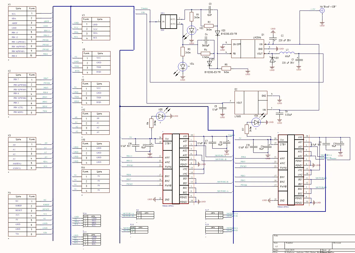
It's simple I use a pulse voltage regulator L7805 in the housing D2Pack
The inclusion scheme is as follows:
Input filters are not particularly important here, but the output should be paid special attention, because if you do not use the output filters in the circuit will be a lot of noise from the chip itself.
2. Providing power to engines (5V and 12V)
Why do I need to make two different types of food? It's simple - in robotics are mainly used two types of electric motors with different supply voltage is 5 Volts and 12 Volts, if fed to 5 Volt electric motor 12 Volts it will not stand. From here and the idea to make two types of power, but to do it on 2 chips I did not want and it is not profitable. So I decided to use the LM2596 chip, which has the following inclusion scheme:
But I used two kinds of feedback on it (through two different dividers), so I used a switch that changes the direction of the current in the circuit, as a result of the output we get two different kinds of power.
In each circuit there is an indicator that shows what mode is now running.
3.Switching I2C, Serial Port and analog inputs
Switching is carried out by creating two buses on the Board, to which the connectors are connected for more convenient Assembly of the robot.
Each analog input has a parallel bus power and ground, all this is done to facilitate the connection of sensors with the robot.
4. Motor control
2 two-channel N-bridge TB6612FNG is responsible for the control, the circuit of each of which is as follows
The whole project is made in Altium Designer 17, the concept of the project is as follows:
For convenient design of boards is very convenient to use the Bus function (bus), this format allows you to create projects to reduce the space in the drawing and make the project more readable.
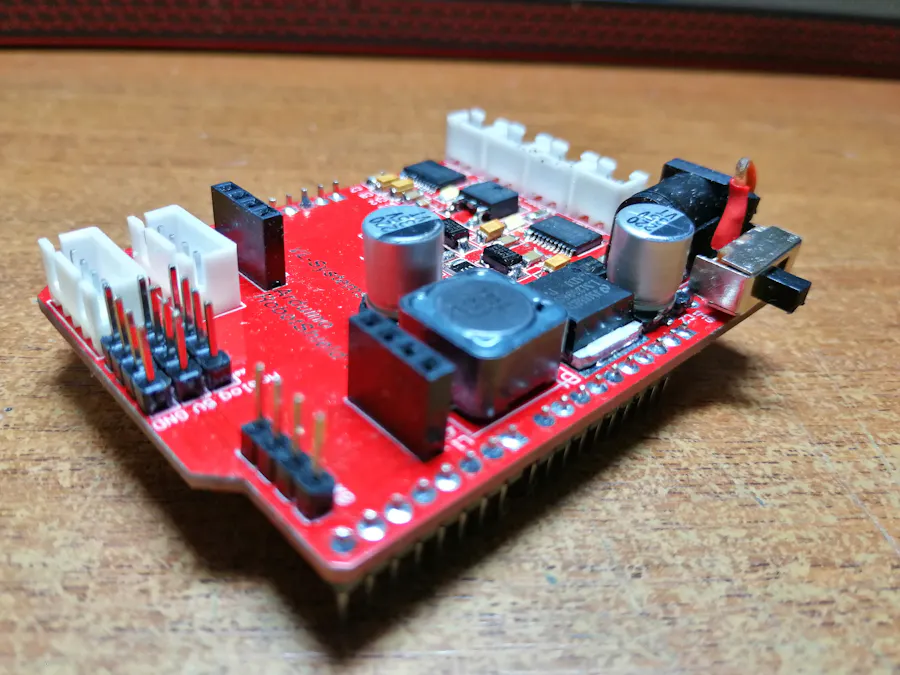
The three-dimensional model can be seen in the figure below
When placing the components I tried to keep the minimum distance to reduce the space on the Board.
And always remember that the filter capacitors should be put as close as possible to the chips.
It remains only to install the components and can be used, after installation the Board proved to be functional.


Comments