#include "mbed.h"
#define SAMPLES_PER_SECOND 180000
#define PPI_CHANNEL (7)
#define ADC_BUFFER_SIZE 1
volatile nrf_saadc_value_t adcBuffer[ADC_BUFFER_SIZE];
volatile bool adcFlag = false;
volatile uint32_t sampleCounter = 0;
void setup()
{
Serial.begin( 9600 );
while ( !Serial );
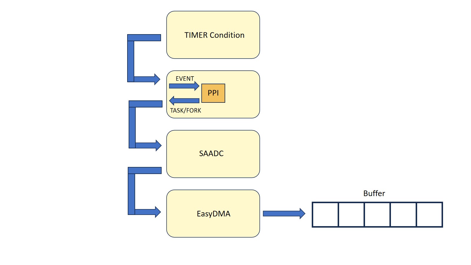
Serial.println( "Arduino Nano 33 BLE (mbedOS) example: Timer -> PPI -> SAADC" );
delay(10000);
initADC();
initTimer4();
initPPI();
}
void loop()
{
__WFI();
__SEV();
__WFE();
static uint32_t previousMillis = 0;
if ( adcFlag )
{
delay(1000);
adcFlag = false;
if ( sampleCounter >= SAMPLES_PER_SECOND )
{
uint32_t sampleCount = sampleCounter;
uint32_t currentMillis = millis();
uint32_t runTime = currentMillis - previousMillis;
Serial.print( "Samples: " );
Serial.print( sampleCount );
Serial.print( " run time: " );
Serial.print( runTime );
Serial.print( " ms A0: " );
Serial.println( adcBuffer[0] );
previousMillis = currentMillis;
sampleCounter = 0;
}
}
}
extern "C" void SAADC_IRQHandler_v( void )
{
if ( NRF_SAADC->EVENTS_END != 0 )
{
NRF_SAADC->EVENTS_END = 0;
adcFlag = true;
sampleCounter++;
}
}
void initADC()
{
nrf_saadc_disable();
NRF_SAADC->RESOLUTION = NRF_SAADC_RESOLUTION_12BIT;
NRF_SAADC->CH[2].CONFIG = ( SAADC_CH_CONFIG_GAIN_Gain1_4 << SAADC_CH_CONFIG_GAIN_Pos ) |
( SAADC_CH_CONFIG_MODE_SE << SAADC_CH_CONFIG_MODE_Pos ) |
( SAADC_CH_CONFIG_REFSEL_VDD1_4 << SAADC_CH_CONFIG_REFSEL_Pos ) |
( SAADC_CH_CONFIG_RESN_Bypass << SAADC_CH_CONFIG_RESN_Pos ) |
( SAADC_CH_CONFIG_RESP_Bypass << SAADC_CH_CONFIG_RESP_Pos ) |
( SAADC_CH_CONFIG_TACQ_3us << SAADC_CH_CONFIG_TACQ_Pos );
NRF_SAADC->CH[2].PSELP = SAADC_CH_PSELP_PSELP_AnalogInput2 << SAADC_CH_PSELP_PSELP_Pos;
NRF_SAADC->CH[2].PSELN = SAADC_CH_PSELN_PSELN_NC << SAADC_CH_PSELN_PSELN_Pos;
NRF_SAADC->RESULT.MAXCNT = ADC_BUFFER_SIZE;
NRF_SAADC->RESULT.PTR = ( uint32_t )&adcBuffer;
NRF_SAADC->EVENTS_END = 0; //prev interrupt events are cleared
nrf_saadc_int_enable( NRF_SAADC_INT_END ); // enables the saadc interrupt after adc conversion
NVIC_SetPriority( SAADC_IRQn, 1UL );
NVIC_EnableIRQ( SAADC_IRQn );
nrf_saadc_enable();
NRF_SAADC->TASKS_CALIBRATEOFFSET = 1;
while ( NRF_SAADC->EVENTS_CALIBRATEDONE == 0 );
NRF_SAADC->EVENTS_CALIBRATEDONE = 0;
while ( NRF_SAADC->STATUS == ( SAADC_STATUS_STATUS_Busy << SAADC_STATUS_STATUS_Pos ) );
}
void initTimer4()
{
NRF_TIMER4->MODE = TIMER_MODE_MODE_Timer;
NRF_TIMER4->BITMODE = TIMER_BITMODE_BITMODE_16Bit;
NRF_TIMER4->SHORTS = TIMER_SHORTS_COMPARE0_CLEAR_Enabled << TIMER_SHORTS_COMPARE0_CLEAR_Pos; //when timer reaches cc[0], clear the timer
NRF_TIMER4->PRESCALER = 0;
NRF_TIMER4->CC[0] = 16000000 / SAMPLES_PER_SECOND; // Needs prescaler set to 0 (1:1) 16MHz clock
NRF_TIMER4->TASKS_START = 1;
}
void initPPI()
{
NRF_PPI->CH[PPI_CHANNEL].EEP = ( uint32_t )&NRF_TIMER4->EVENTS_COMPARE[0];
NRF_PPI->CH[PPI_CHANNEL].TEP = ( uint32_t )&NRF_SAADC->TASKS_START; //starts adc task, helps synchronizing the ADC conversion with Timer 4's events.
NRF_PPI->FORK[PPI_CHANNEL].TEP = ( uint32_t )&NRF_SAADC->TASKS_SAMPLE;
NRF_PPI->CHENSET = ( 1UL << PPI_CHANNEL );
}


Comments