


Hardware components | ||||||
_ztBMuBhMHo.jpg?auto=compress%2Cformat&w=48&h=48&fit=fill&bg=ffffff) |
| × | 1 | |||
 |
| × | 1 | |||
 |
| × | 2 | |||
| × | 2 | ||||
 |
| × | 4 | |||
Software apps and online services | ||||||
 |
| |||||
Hand tools and fabrication machines | ||||||
 |
| |||||
 |
| |||||
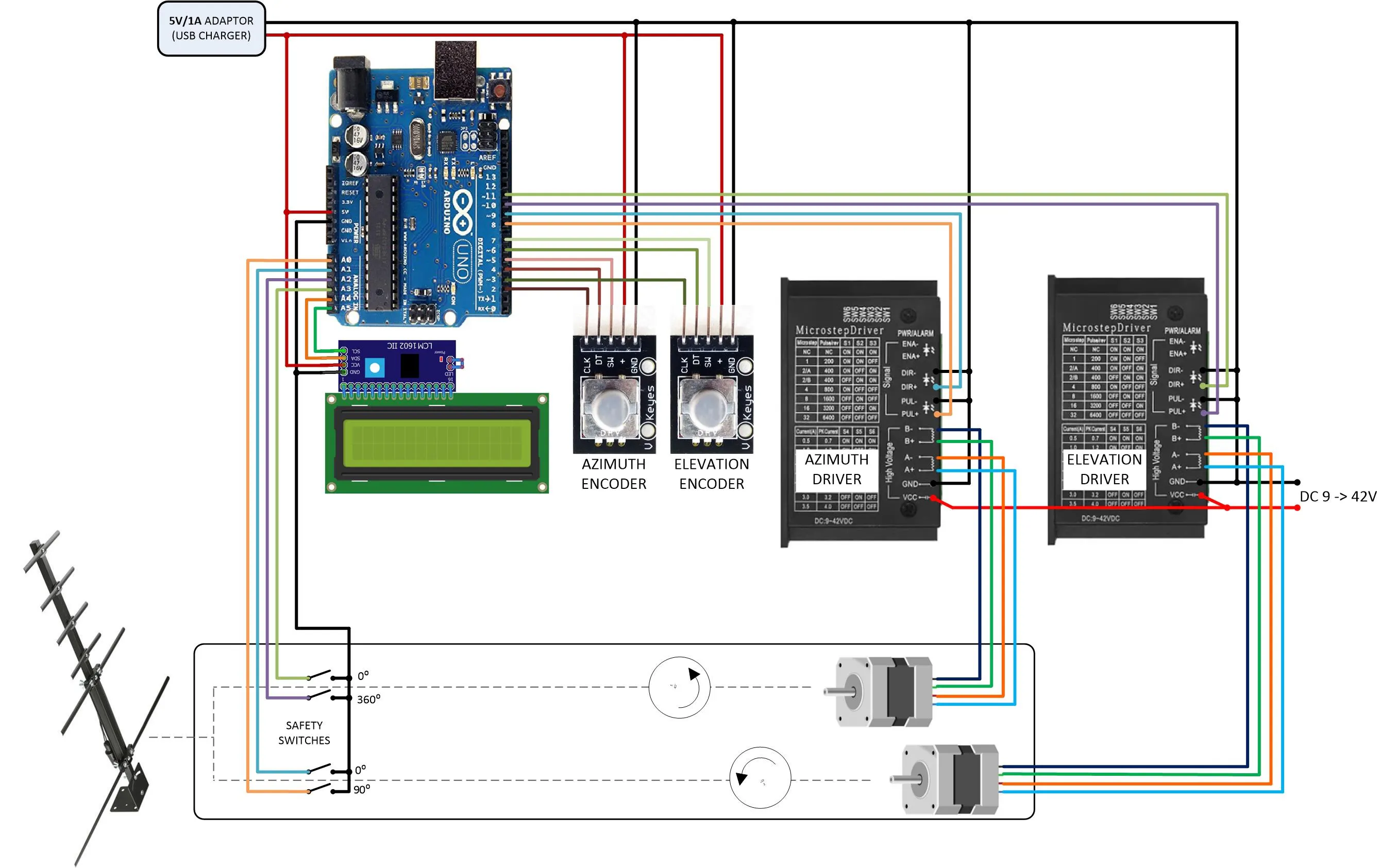
This project aims to control a (home made) rotator or even a PAN-TILT head (for CCTV camera) equipped with stepper motors, with an Arduino controller.
A Pan-Tilt head is an excellent choice for an antenna rotator. These mounts usually employ synchronous AC motors, sometimes DC motors, and rarely stepper motors. I will approach the stepper motors variant. Speaking of different projects, I made one for rotors with feedback potentiometers, which works splendid, and one for AC/DC Pan-Tilt heads without feedback. Check them out if you have such a rotor (the commercial antenna rotor or a home-made one).
- potentiometer equipped version: https://www.hackster.io/viorelracoviteanu/antenna-rotator-controller-compatible-with-tracking-software-48f9cd
- no feedback version:... to be developed ...
The stepper motor rotators usually don't have a feedback mechanism. Normally if we want to know where the antenna really is at any time, a potentiometer or an encoder is connected to the motor output shaft, with gears. This device is read by the antenna controller and the position is displayed. A stepper motor converts electrical pulses into precise, discrete mechanical steps of rotation, allowing for accurate control of position and speed without complex feedback systems. Each pulse moves the motor a fixed, small angle, and by counting the pulses, the position of the motor can be precisely controlled. To position the antenna in the right direction, we must know the number of pulses it takes the motor to make a full turn (360⁰) and then divide it to the angle we need to move. Say the PAN-TILT mount needs 4096 pulses for a full turn. This means for one pulse, the motor rotates 0.088⁰ (360/4096). The down side is one can never be very sure, in the absence of a true position feedback, where the antenna actually is. It is possible, due to external factors (load, inertia, wind…) that the motor skips or jump steps, the antenna travels more or less than desired and the errors may accumulate over time. This shortcoming can be cancelled by resetting the controller after an extensive period of use, and bringing the antenna position back to zero. The controller has the ability to move the antenna automatically, when connected to a computer via USB. It works with almost all Satellite Tracking Programs and uses EASYCOMM protocol, 9600bauds. EASYCOMM1 only outputs data to the controller, EASYCOMM2 also reads back the antenna position and puts it on the screen. Both works. There is also the possibility to point the antenna manually, with the help of two rotary encoders, in Azimuth and Elevation. I use mainly PstRotator which I find exceptionally good, it also controls the radio (you have to buy a license which is cheap). The good old Orbiton works with a DDE to Serial plugin. HamRadioDeluxe which is a very good one, only works on EASYCOMM1, great pity, because it doesn’t show the antenna position. I guess it implements a custom EASYCOMM language and doesn’t understand my antenna feedback. SatPC32 works, it’s a bit tricky to set it up, it’s a good one, I’m not a big fan.
HOW THE CONTROLLER WORKSFirst of all, you must input in the code number of pulses per full turn (360⁰ and 90⁰) for both the azimuth and the elevation. You will find this information in the motor’s documentation or on its label. Without it it’s hard to guess. Look for this section at the beginning:
Change the values with your own. There is also a parking position you can customize. Input the coordinates you want the antenna to go when not in use. More of this later.
This code uses smooth movements for an elegant operation, without shaking the antenna. It will accelerate the motor up to full speed towards the target, and, as it gets nearer, it will start to decelerate to full stop. You can change the speed and acceleration in the section below: Speed 1000 for example is very high and most motors will buzz and won’t turn. Acceleration should be 80-90% of speed. The closer to speed value, the faster it accelerates. Upload the code to your Arduino. You only have to do this once.
At boot time, the controller has no idea where the antenna is. It may be left on a certain position from the previous session. It could be on 90⁰, 123⁰ or even 0⁰, absolutely no information. If we don’t know the initial position, we can’t calculate the future movement. This is why we take the worst-case scenario, the antenna is all the way around, 359⁰/90⁰. The controller activates the motors for the maximum number of pulses (you just input above) in order to bring the antenna to zero. Even if the antenna was closer than that, you still have to wait until it hits the end-stop. This way we know for sure, at the end of this start-up phase, that the antenna is at 0⁰/0⁰, and from this point onwards we can precisely control future positions. The code and the schematic support the connection of safety switches. The rotor must have a hard stop at the end of the turn or safety switches, otherwise it may keep spinning until it breaks the wires. If you have a mechanical stop, the safety switches are not mandatory, the code can do without them.
The display shows the antenna position, target position and the motor movement.
The motor movement is represented by arrows pointing in the direction of travel.The “ = ” indicates motor STOP. The antenna reached the target.Once the motor starts moving, it doesn’t stop until it reaches the target and it doesn’t accept any other command. Only after it stops, will it take another input.
1. When using the computer control it’s very straight forward. Plug the USB cable, launch the satellite tracking software. Select the COM port of the Arduino, EASYCOMM (preferably II) protocol, 9600bd, and you’re good to track satellites with your rotator. For PstRotator select K3NG(EASYCOMM II).
2. Bear in mind that the controller always waits for computer control. If you want to use the manual control, first you have to activate it by pressing the Azimuth Encoder Push.
The " ∗ " symbol will appear, meaning the controller is ready for manual input. Rotate the Azimuth and the Elevation encoder and watch the target coordinates changing on the display. Press again the Azimuth Encoder Push and the antenna will start moving towards the target. There will be arrows showing the direction of movement.
3. The PARK position. There is the possibility to send the antenna directly to a pre-programmed position. This position can be one with the least wind resistance, or anything you can think of. For example, just before you finish your satellite session, put the antenna in the parking position, then turn off the controller. To activate the parking position, press the Elevation Encoder Push.
The " % " symbol will appear and the new coordinates are automatically activated.
Check out the video I made explaining the build and functionality of this project:
My personal project web page https://racov.ro/index.php/2025/11/08/arduino-antenna-controller-for-stepper-motors-rotators/
Arduino controller for rotators with feedback potentiometers https://www.hackster.io/viorelracoviteanu/antenna-rotator-controller-compatible-with-tracking-software-48f9cd
Note:
1. You can use encoders with pull-up resistors, or just simple encoders. Both works fine.
2. Be aware that some drivers (as TB6600) use micro stepping, this means it will multiply the number of steps according to the settings.
3. If you need Azimuth only, that’s OK; just don’t put the Elevation components and it will work just fine.
HAPPY SATELLITE HUNTING!!!
Please feel free to use this code any way you want. I can’t take any responsibility for the misuse of this project. If you have any questions or difficulties, send me an email to YO3RAK@gmail.comI will try to solve small issues the best I can. Cheers!


Comments