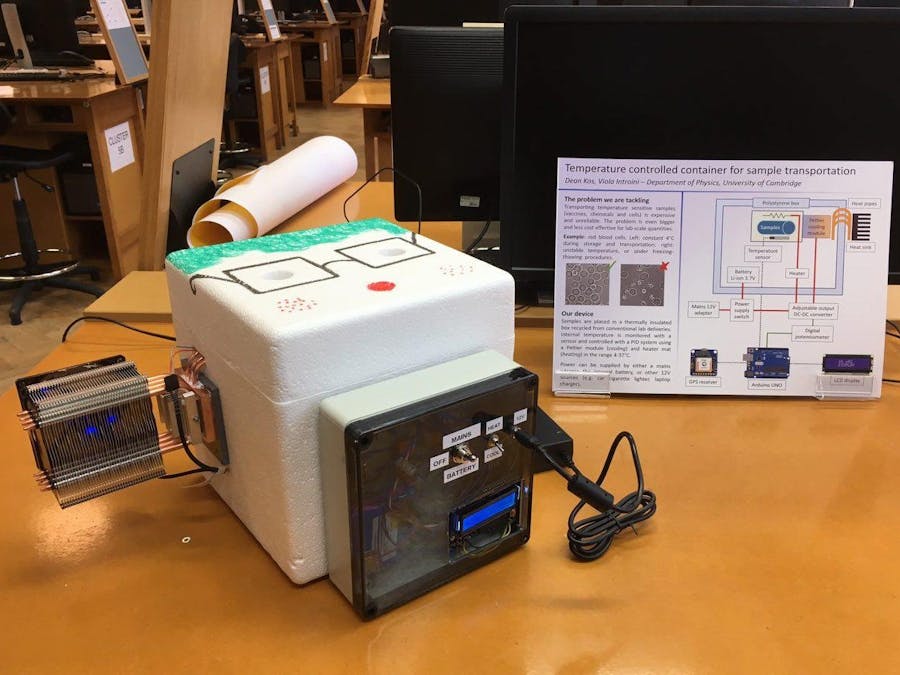
Mr ThermoParcel: Temperature Controlled Container for Sample TransportationThe aim of is to develop a temperature controlled container that can be used to safely transport sensitive samples with a conventional mail service. Our prototype device, called Mr ThermoParcel, works within the range of temperature 4-37 °C, and can powered by either a mains adapter, internal battery, or other 12V sources such as a car cigarette lighter or laptop charger.
The Genesis of Our ProjectOur idea originates from a real problem that we faced in our academic research: the safe exchange of temperature-sensitive biological samples with collaborators. Viola works on the malaria disease, and there is often the need to send or receive blood samples. However, if the samples are not kept at the correct temperature during storage and transportation, they can easily degrade and become useless. This is all the more frustrating when samples contain precious types of blood that have a special response to malaria and come from rare patients.
The common method to send blood samples of this type is to completely freeze them before shipping, use a standard courier for frozen goods, and then carefully defrost them after delivery. Apart from still being expensive, such a system is far from ideal, since freezing/defrosting always alters or damages parts of the samples, and the defrosting process itself follows a specific protocol that requires additional chemicals. Furthermore, items often get delivered to University at the campus parcel depot, where inappropriate storage conditions and delivery notification delays are frequent causes of sample degradation.
Design conceptWe integrated a temperature control system in a conventional polystyrene container of the size of a small parcel, reused from a delivery of chemicals. We optimised and tested it with blood samples, but the same system could be used for a vast range of other biological materials such as cells, culture media, temperature sensitive chemicals, emulsions, and enzymes, or even adapted for solid items.
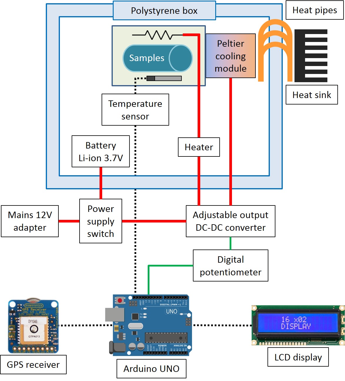
The concept of the system is shown in Figure 1. Cooling is achieved with a Peltier module, with the cold side attached to a small sample box inside the polystyrene container, and the hot side connected to an external heat sink. Heating is performed with a heater mat placed inside the sample box. Temperature is constantly monitored using a sensor in contact with the samples, and the heating/cooling intensity is regulated by an Arduino controller.
Figure 1. Design concept of the temperature controlled container.
Container hardware design
The external container is a polystyrene box with dimensions 250x250x250mm and wall thickness 45mm on all sides, which is a common type of box used in lab deliveries with standard mail services. A plastic enclosure (125x70x40mm) is placed inside, and contains two 50mL centrifuge tubes. These tubes act as secondary packaging according to regulations for Biological and Infectious Substances, Category B UN3373 (link: http://www.un3373.com/info/regulations/ ). The primary samples are six 2mL Eppendorf tubes containing specimens, separated by absorbent tissue to prevent any leaking. Mr ThermoParcel is able to store up to 50mL of liquid samples by replacing hard secondary packaging with flexible pouches that can contain a bigger amount of specimens, e.g. up to three o four 15mL tubes (link: https://www.alphalabs.co.uk/laboratory-products/consumables/sample-handling/sample-transport/95kpa-pouches ). To improve heating/cooling uniformity inside the internal box, and ensure thermal contact between the copper sheet, samples and temperature sensor, we poured an electrically insulating, solid-setting gel around the samples. The inner box containing samples is shown in Figure 2.
Figure 2. Samples inside a secondary packaging with absorbent material to prevent any leakage. The blue transparent gel ensures good thermal contact with the samples and temperature sensor.
Cooling and Heating system
Internal temperature is monitored with a 100Ohm Pt resistance thermometer (or Resistance Temperature Detector, RTD) placed in contact with the samples, and controlled with a PID system using a Peltier module (cooling) or heater mat (heating). In order to dissipate outside the box the heat from the Peltier, the hot side of the Peltier module is put in thermal contact with an external piece of copper and a heat sink (CPU cooler) via three copper heat pipes. The cold side is attached to a thin copper sheet that passes through the box, cooling down the samples uniformly. Details of the thermal coupling are shown in Figure 3.
The heating mat is placed inside the inner enclosure in contact with the temperature sensor and the samples.
1 / 3 • Figure 3. Cooling and heating system. The Peltier module is sandwiched between the internal copper block and the copper sheet inside the box, and is not visible in the photographs. The brown-coloured foil on the right in this image is one side of the heater mat.
Cooling and heating regulation
The Peltier module used by Mr ThermoParcel is rated for 3.9A and 7.6V at maximum cooling power. To control the temperature effectively, the amount of power delivered to the Peltier module is managed electronically using the PTN78020W step-down adjustable switching regulator. The regulator accepts an input voltage in the range 7-36V, and produces an output in the range 2.5-12.6V, with the limitation that the output cannot exceed the input minus 2V. The output voltage is adjusted by setting a certain value of resistance between two regulation pins, according to the table in the device datasheet. Mr ThermoParcel employs the MCP41100 100kOhm digital potentiometer, controlled by Arduino, to electronically regulate the output voltage based on the temperature reading. Since the entire output voltage range of the PTN78020W requires a variation in voltage in excess of 1MOhm, a voltage is applied to the Peltier module even when the digital potentiometer is set to 100kOhm, so the Peltier module can't be "turned off" using the digital potentiometer alone. The same regulation concept applies to the heating performed with the heater mat. The mat is simply a resistor that dissipates current as heat, and regulating the voltage is a direct way to control the delivered power.
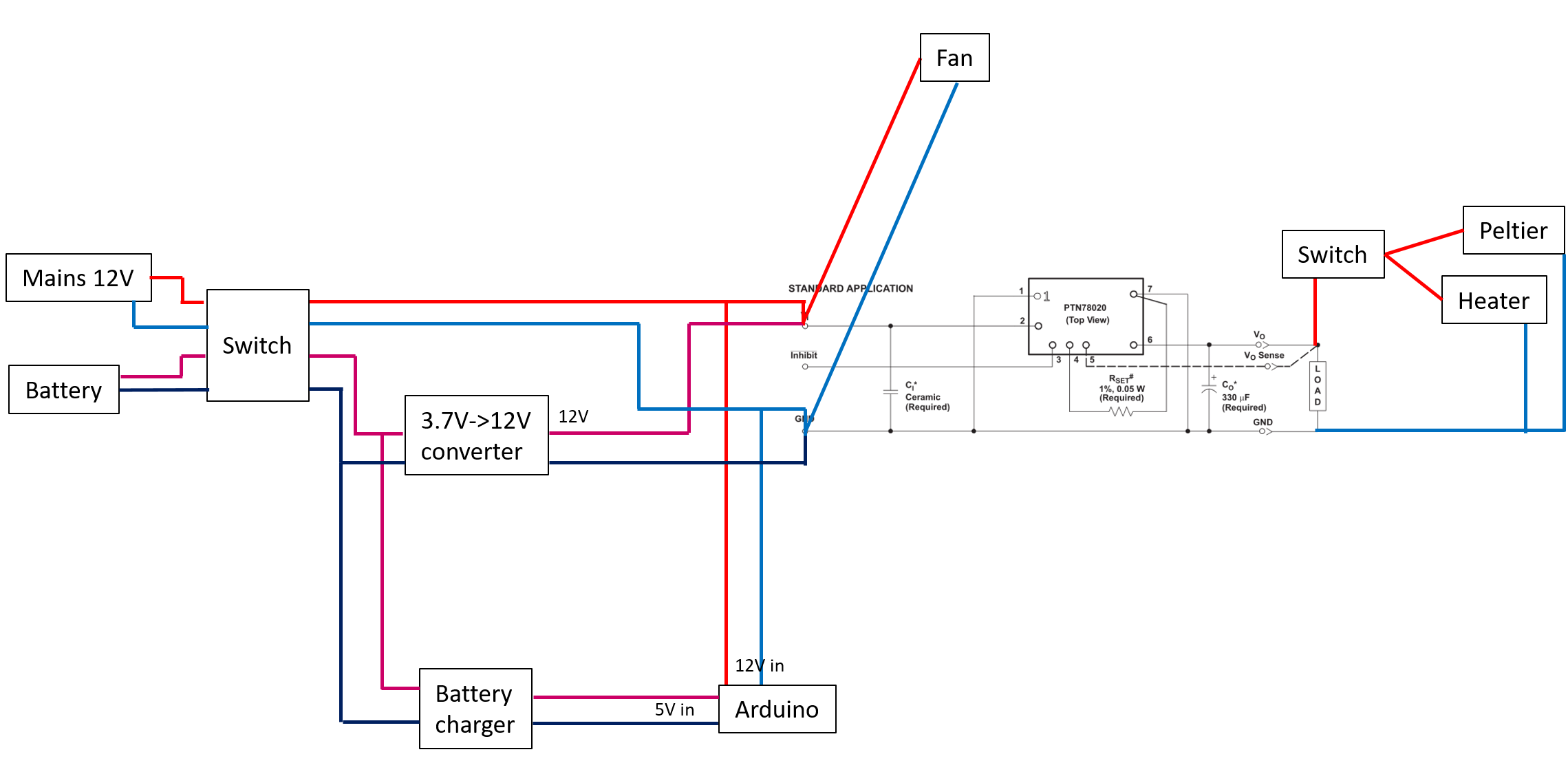
Power supply
A 12V DC power supply is used to directly power the PTN78020W when Mr ThermoParcel is near a mains power socket. This allows for up to 10V output, which is sufficient to drive the Peltier at maximum power, and the heater mat at sufficient power for the purposes of the project. Given the 7-36V input range of the PTN78020W regulator, Mr ThermoParcel can be also driven with most DC power supplies used for laptops and other electronic devices, as well a the cigarette lighter sockets found in cars. When external power is not available, Mr ThermoParcel is powered by a 3.7V, 10400mAh Li-ion battery. The battery still powers the PTN78020W regulator, but to reach the input voltage required to drive the Peltier module (10-12V at the PTN78020W input), the XL6019 step-up DC-DC converter is first connected at the battery output.
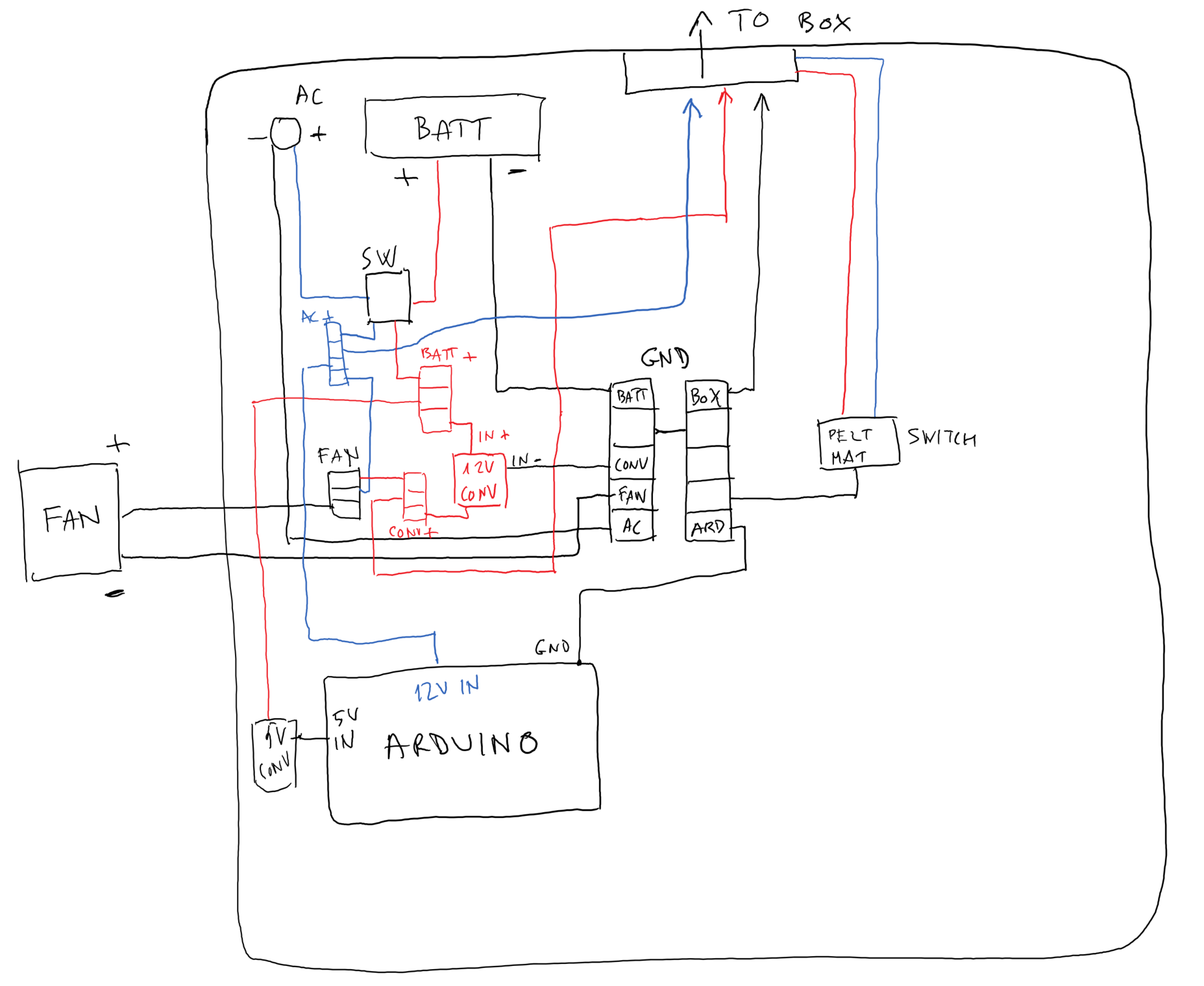
Arduino wiring
Power is supplied to Arduino directly from the 12V external input if available, via the jack socket on the board. If using the internal battery, a similar voltage is set at the socket using the output from the XL6019 converter.
Arduino regulates the power delivered to the Peltier module/heater mat by controlling the resistance of the digital potentiometer. Wiring is done according to the instructions in sleemanj's MCP41 series library, with the potentiometer in variable resistor configuration. Arduino is also connected to the Adafruit MAX31865 Pt100 RTD amplifier, used to read the temperature sensor, and to the Adafruit RGB LCD Shield, used to display the temperature data and system operation. These are both wired according to the thorough Adafruit documentation found on the product pages.
Software
All Adafruit modules connected to Arduino are operated with their respective libraries, and the digital potentiometer with sleemanj's MCP41 series library. The core functionalities of the Arduino code in Mr ThermoParcel are related to the temperature control, which is implemented with a PID closed loop system. The temperature set point is provided by the user via the LCD display shield buttons. Each measured temperature reading is then used to obtain the deviation from the set point, and thus calculate the PID value that is fed to the digital potentiometer to regulate the cooling/heating power. An external physical toggle switch determines whether the power output is directed towards the Peltier module (cooling) or the heater mat (heating). Since there are no electronic switches in the system, a distinction is made is the code between a heating mode and a cooling mode, and the user must select the appropriate mode using the LCD display shield buttons. This distinction ensures that the calculated PID value has the correct sign. During our tests we tried a range of values for the PID factors, and observed that the P term alone was sufficient in most situations to stay within ±0.5°C from the set point, so we eventually removed the I and D factors. This is probably due to the relatively large heat capacity of the samples and internal gel-filled box, that make temperature changes slow (typically an average of 0.02°C/s in the fastest regimes).
PerformanceWhen mains powered, Mr ThermoParcel cools down to 4°C when starting from a room temperature of 21-23°C within about 1h. A temperature of 8-10°C is reached within the first 20 minutes. Starting again from room temperature, and using the heater mat, 37°C are reached within about 10 minutes. All temperatures are maintained at the setpoint within ±0.5°C.
When powered by the internal battery only, approximately 10°C is the minimum temperature that can be reached, in a time of 1.5-2h. With the heater mat, 37°C can still be obtained but in 40-60 minutes. These limitations are due to the discharge rate of the battery: the Li-ion battery in Mr ThermoParcel is rated for 7A maximum discharge current at 3.7V, but given the step-up conversion to 10-12V the discharge current would need to be higher to maintain the maximum power of the Peltier module. Since the battery contains self-protection circuits which cut off its output in case of current overload, the system cannot function if the cooling/heating system attempts to draw a current larger than the maximum rating. When operating via the battery, the power draw is limited by the software to a safe level. This limitation is purely due to the battery being used here, and batteries with higher discharge rate are widely available. Alternatively, a Li-ion battery with 3 cells in series and a nominal voltage of 11.1V would solve the problem and also eliminate the need for a step-up DC converter.
1 / 2 • Figure 4. View of the front panel of Mr ThermoParcel, showing the LCD display shield and wiring.
In its current development stage, our device cannot be shipped, mainly because of the size and moving parts of the CPU cooler, and the robustness of the construction. However, once the heat sink is replaced by a passive cooling system and a 95k Pa secondary packaging is employed, Mr ThermoParcel could be put in an appropriate rigid container for safe transportation, fulfilling all the requirements of standard couriers for shipping samples by plane and all other transport means.
With core aim of the achieved, other components could be added to extend the functionality of the device. The temperature profile during transportation could be stored in a local memory for later verification, or sent directly to the user via SMS at regular intervals using a GSM Arduino module. A GPS receiver could also be included for independent parcel tracking and timely collection at delivery.


_ztBMuBhMHo.jpg?auto=compress%2Cformat&w=48&h=48&fit=fill&bg=ffffff)


Comments