Vikram Tokala
Published © GPL3+

Smart Bicycle

Developing and mounting sensors on a bike.

AdvancedShowcase (no instructions)14,795
Smart Bicycle

Things used in this project

Hardware components

Ultrasonic Sensor - HC-SR04 (Generic)
×3
Hall Effect Sensor
Hall Effect Sensor
×1
RGB Backlight LCD - 16x2
Adafruit RGB Backlight LCD - 16x2
×1
DHT22 Temperature Sensor
×1
Arduino UNO
Arduino UNO
×1
5 mm LED: Red
5 mm LED: Red
×4
Shift Register- Serial to Parallel
Texas Instruments Shift Register- Serial to Parallel
×1
Adafruit Ultimate GPS Logger shield
×1
Pulse Train Hat Pulse sensor
×1

Software apps and online services
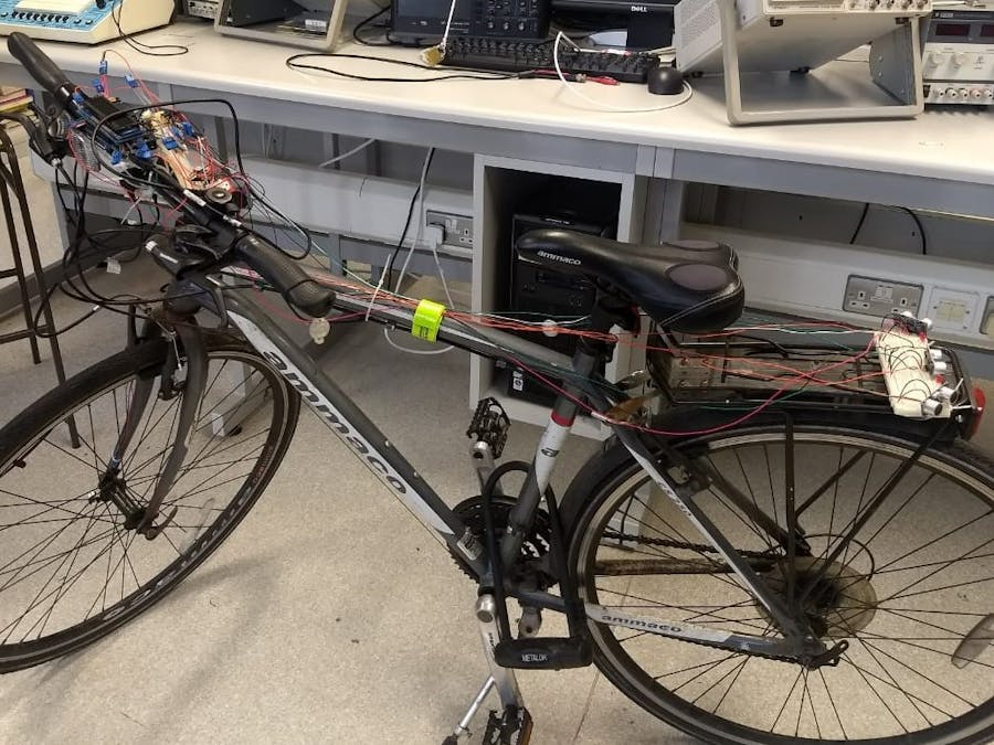
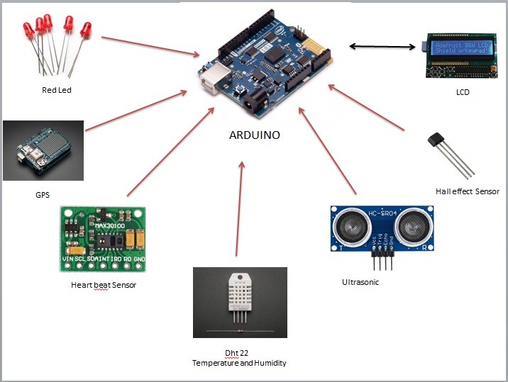
Arduino Web Editor
Arduino Web Editor

Story

Read more

Schematics

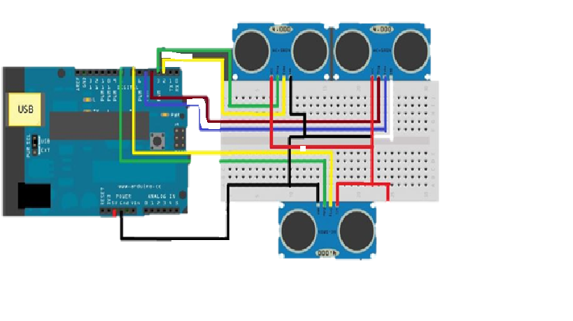
connection of ultrasonic sensors

These sensors use ultrasonic radiation to indicate any obstacle and we use three sensors to indicate any vehicles coming from behind

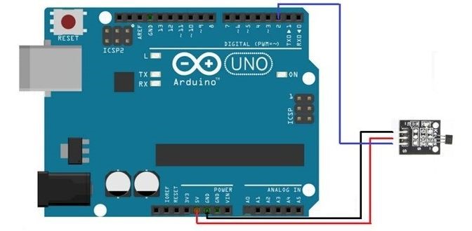
connection of hall effect sensors

thia is used to cacualte the RPM .It is placed on the cranck of the front tyre and is indiactes the detction of magentic field
The red line indicates the Vcc pin which is connected to 5V on the Arduino UNO Board and the Blackline indicates ground which is connected to the GND pin on the Arduino board. Then the Blue line indicates the digital input of the sensor to the Digital I/O pin on the sensor

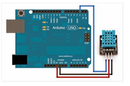
Temperature and Humidity sensor

The Black wire indicates the Ground pin which is connected to the ground pin on the Arduino UNO.
The Red wire indicates the Vcc pin which is connected to the 5V pin on the Arduino UNO.
The Blue wire indicates the Data input pin which is connected to the one of Digital I/O pins on the Arduino UNO.

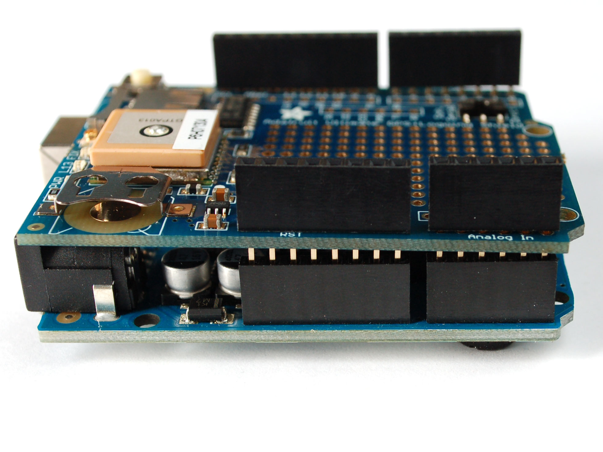
GPS ULTIMATE LOGGER SHIELD CONNECTED TO ARDUINO UNO

The ultimate GPS logger shield is assembled with Arduino shield stacking headers. The Ultimate GPS logger shield also uses I2C interface for connecting with Arduino UNO. The stacking headers provide a ‘pass-thru’ connection so multiple shields can be attached on the top

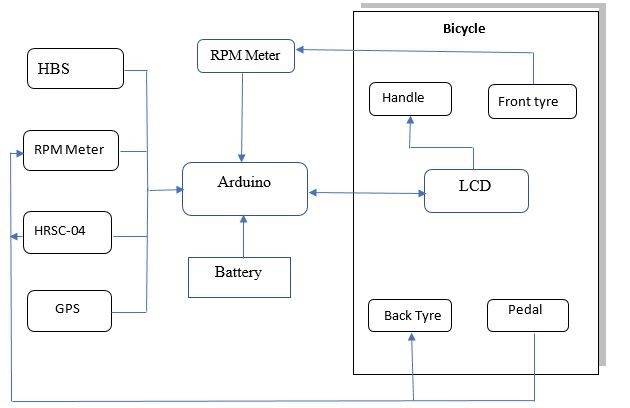
Functional diagram of the smart bike

The Smart Bike architecture diagram depicts how the sensors are interfaced and mounted on to the bike. Arduino UNO microcontroller (ATMega328P) is used as central hardware unit which is interfaced with the sensors used in the project. Heartbeat sensor and Temperature sensor are mounted along with the Arduino on to the handle bar and the LCD display which is on the Arduino UNO will display the temperature, humidity and heart rate. The Heartbeat sensor uses the I2C as the interface with the Arduino.
The Hall effect sensors are connected on the pedal and on the front tyre fork and the magnets are connected to the spikes on the front tyre and opposite to the pedal pad when the sensor passes through the magnet the voltage fluctuates giving rise to the number of times the Revolution per second which is converted into speed and distance traveled. These sensors are wired to the Arduino UNO which is present at the handlebar.
Ultrasonic ranging module is used to obtain the non-contact ranging information. There are a total of three ultrasonic sensors that are used in the project. These sensors are mounted on the rear tyre fork one on each side to cover the maximum field of view indicating the vehicles or obstacle’s that are approaching the bike.
GPS ultimate logger shield is used to track the whereabouts of the bike’s location and is interfaced with the Arduino UNO on the handlebar. All the coordinates will be logged on to the SD card.
The LEDs are also mounted on the back-tyre fork to indicate the left and right turnings at the time of ride so as avoid any accidents that can be caused due to overlooking.
The functional diagram of the project would be depicted as shown below where all the sensors are connected to the Arduino UNO and the LCD display takes the information from the Arduino and the sensors.
The Ultrasonic sensors are used to indicate an object that is approaching towards the vehicle. Three ultrasonic sensors are used in the project and are optimized such that a maximum field of view is obtained. The working of the three ultrasonic sensors is the same as explained in the background theory and all the three sensors are operated simultaneously to maintain perfect synchronization between sensors.

Architecture diagram:

The system is designed keeping various parameters in mind like cadence, speed, heart rate, temperature, humidity, and non -contact range detection interfacing them using the Arduino and displaying the measured parameters are displayed on an LCD display. LEDs are used to indicate right and left turns. Arduino UNO is chosen as it is ideal for interfacing all the sensors in a single platform

Code

software code for the smart bicycle when all the sensors are interfaced on to the bicycle

Arduino
#include <Wire.h>
#include <Adafruit_RGBLCDShield.h>
#include <utility/Adafruit_MCP23017.h>
Adafruit_RGBLCDShield lcd = Adafruit_RGBLCDShield();
#include <DHT.h>;
#define USE_ARDUINO_INTERRUPTS true    
#include <PulseSensorPlayground.h>   


#define I2C_ADDR 0x3F
#define RED 0x1
#define YELLOW 0x3
#define GREEN 0x2
#define TEAL 0x6
#define BLUE 0x4
#define VIOLET 0x5
#define WHITE 0x7
#define DHTPIN 2
#define DHTTYPE DHT22   
DHT dht(DHTPIN, DHTTYPE);
const int PulseWire = 0;       
const int LED13 = 13;          
int Threshold = 550;           


PulseSensorPlayground pulseSensor;  


int trigPin1=10;
int echoPin1=3;

int trigPin2=4;
int echoPin2=5;

int trigPin3=6;
int echoPin3=7;


int chk;
float hum;  
float temp; 


void setup() {
  
  Serial.begin(115200);
   pulseSensor.analogInput(PulseWire);   
   pulseSensor.blinkOnPulse(LED13);       
   pulseSensor.setThreshold(Threshold);   

  
   if (pulseSensor.begin()) {
    Serial.println("We created a pulseSensor Object !");
   }
  dht.begin();
  
  lcd.begin(16, 2);
  lcd.setCursor(0,0);
    
  lcd.setCursor(0,1);
   lcd.setBacklight(WHITE);
  
  
  pinMode(trigPin1, OUTPUT);
  pinMode(echoPin1, INPUT);
  pinMode(trigPin2, OUTPUT);
  pinMode(echoPin2, INPUT);
  pinMode(trigPin3, OUTPUT);
  pinMode(echoPin3, INPUT);
  
  
}


uint8_t i=0;
uint8_t new_buttons=BUTTON_LEFT;


void loop() {
   
   
  uint8_t buttons = lcd.readButtons();
  if(buttons)
     new_buttons=buttons;
  
  
  hum= dht.readHumidity();
  temp= dht.readTemperature();

    long duration1, distance1;
  digitalWrite(trigPin1, LOW);  
  delayMicroseconds(2); 
  digitalWrite(trigPin1, HIGH);
  delayMicroseconds(10); 
  digitalWrite(trigPin1, LOW);
  duration1 = pulseIn(echoPin1, HIGH);
  distance1 = (duration1/2) / 29.1;
  
     
  long duration2, distance2;
  digitalWrite(trigPin2, LOW);  
  delayMicroseconds(2); 
  digitalWrite(trigPin2, HIGH);
  delayMicroseconds(10); 
  digitalWrite(trigPin2, LOW);
  duration2 = pulseIn(echoPin2, HIGH);
  distance2= (duration2/2) / 29.1;
    
  long duration3, distance3;
  digitalWrite(trigPin3, LOW);  
  delayMicroseconds(2); 
  digitalWrite(trigPin3, HIGH);
  delayMicroseconds(10); 
  digitalWrite(trigPin3, LOW);
  duration3 = pulseIn(echoPin3, HIGH);
  distance3= (duration3/2) / 29.1;


  if (new_buttons) {
    lcd.clear();
    lcd.setCursor(0,0);
    if (new_buttons & BUTTON_UP) {
      lcd.print("Humidity:");
      lcd.print(hum);
      lcd.setCursor(0,1);
      lcd.print("Temperture:");
      lcd.print(temp); 
      lcd.setBacklight(RED);
    }
       if (new_buttons & BUTTON_DOWN) {
       lcd.clear();
       lcd.setCursor(0,0);
       lcd.print("S1");
       lcd.print(distance1);
       lcd.setCursor(7,0);
       lcd.print("S2");
       lcd.print(distance2);
       lcd.setCursor(0,1);
       lcd.print("S3");
       lcd.print(distance3);
      
      } 
      int myBPM = pulseSensor.getBeatsPerMinute();  
                                           

if (pulseSensor.sawStartOfBeat()) {            
 Serial.println("♥  A HeartBeat Happened ! "); 
 Serial.print("BPM: ");                         
 Serial.println(myBPM);                         
}


        if (new_buttons & BUTTON_LEFT){
            lcd.setCursor(0,0);
            lcd.print("BPM:");
            lcd.print(myBPM);

        }
      
  Serial.print ( "Sensor1  ");
    Serial.print ( distance1);
    Serial.println("cm");
    Serial.print("Sensor2  ");
    Serial.print(distance2);
    Serial.println("cm");
    Serial.print("Sensor3  ");
    Serial.print(distance3);
    Serial.println("cm");
      
      
      }
}


Credits

Vikram Tokala

Vikram Tokala

0 projects • 10 followers
Electronics enthusiast with zeal to add something new to enviroment.

Comments