

Hardware components | ||||||
| × | 1 | ||||
| × | 1 | ||||
| × | 6 | ||||
| × | 1 | ||||
 |
| × | 1 | |||
 |
| × | 1 | |||
 |
| × | 1 | |||
 |
| × | 120 | |||
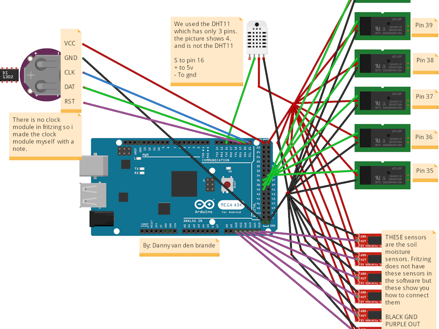
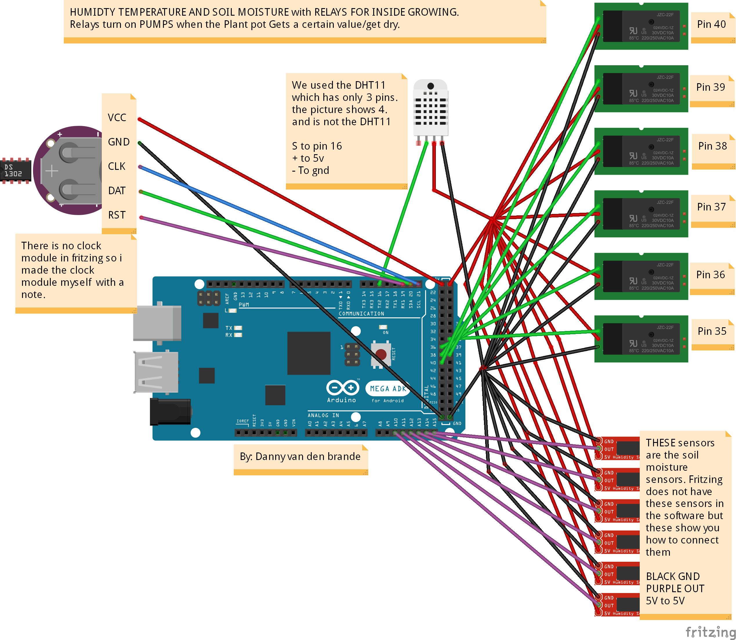
Hi peeps, I created a Prototype Plant watering system with weather station on a TFT LCD for indoor growing. Of Course you can build it to use it outdoors to.
This projects works but is just the basis for a bigger project. From here you can add some other stuff.
Solenoid electric magnetic valves, pumps, or whatever you want to use to water the plants. I would go for the valves, I am pretty new to Arduino and electronics but i am not new to hacking so I know codes.
This code is not really super and needs some more work and some fixes as well as the whole project, but I leave that to the public, I built the heart, and the interface. If you build it like the schematic and upload the code it will work right away.
There is also a real time clock and date. If you build something from it please share it in the comments.
The Schematic is a little bit Messy but Should not be to hard to figure out. The code and project needs some more work, but the basics that you need to begin with it are there.
Good luck!
There is a English and Dutch Code.
//Author Danny van den brande.

#include "DHT.h"
#include <SPFD5408_Adafruit_GFX.h>    // Core graphics library
#include <SPFD5408_Adafruit_TFTLCD.h> // Hardware-specific library
#include <SPFD5408_TouchScreen.h>
//                                    BEGIN CLOCK
#include <DS1302RTC.h>//clock module DS1302
#include <Time.h>//Need for clock module
#define DS1302_SCLK_PIN   21    // Arduino pin for the Serial Clock
//PIN 21 (SCLK_PIN) = CLK on CLOCK and SCL on arduino
#define DS1302_IO_PIN     20    // Arduino pin for the Data I/O
//PIN 20 (IO_PIN) = DAT on CLOCK and SDA on arduino
#define DS1302_CE_PIN     19    // Arduino pin for the Chip Enable
//PIN 19 (CE_PIN) = RST on CLOCK and TX1 on arduino for this you can define any free Digital pin.
#define bcd2bin(h,l)    (((h)*10) + (l))
#define bin2bcd_h(x)   ((x)/10)
#define bin2bcd_l(x)    ((x)%10)

#define DS1302_SECONDS           0x80
#define DS1302_MINUTES           0x82
#define DS1302_HOURS             0x84
#define DS1302_DATE              0x86
#define DS1302_MONTH             0x88
#define DS1302_DAY               0x8A
#define DS1302_YEAR              0x8C
#define DS1302_ENABLE            0x8E
#define DS1302_TRICKLE           0x90
#define DS1302_CLOCK_BURST       0xBE
#define DS1302_CLOCK_BURST_WRITE 0xBE
#define DS1302_CLOCK_BURST_READ  0xBF
#define DS1302_RAMSTART          0xC0
#define DS1302_RAMEND            0xFC
#define DS1302_RAM_BURST         0xFE
#define DS1302_RAM_BURST_WRITE   0xFE
#define DS1302_RAM_BURST_READ    0xFF
#define DS1302_D0 0
#define DS1302_D1 1
#define DS1302_D2 2
#define DS1302_D3 3
#define DS1302_D4 4
#define DS1302_D5 5
#define DS1302_D6 6
#define DS1302_D7 7
#define DS1302_READBIT DS1302_D0 // READBIT=1: read instruction
// Bit for clock (0) or ram (1) area,
// called R/C-bit (bit in address)
#define DS1302_RC DS1302_D6

// Seconds Register
#define DS1302_CH DS1302_D7   // 1 = Clock Halt, 0 = start

// Hour Register
#define DS1302_AM_PM DS1302_D5 // 0 = AM, 1 = PM
#define DS1302_12_24 DS1302_D7 // 0 = 24 hour, 1 = 12 hour

// Enable Register
#define DS1302_WP DS1302_D7   // 1 = Write Protect, 0 = enabled

#define DS1302_ROUT0 DS1302_D0
#define DS1302_ROUT1 DS1302_D1
#define DS1302_DS0   DS1302_D2
#define DS1302_DS1   DS1302_D2
#define DS1302_TCS0  DS1302_D4
#define DS1302_TCS1  DS1302_D5
#define DS1302_TCS2  DS1302_D6
#define DS1302_TCS3  DS1302_D7


// Bit for reading (bit in address)
#define DS1302_READBIT DS1302_D0 // READBIT=1: read instruction

#define DHTPIN 16     // what pin we're connected to
#define DHTTYPE DHT11 // DHT 11
#define DS1302_READBIT DS1302_D0 // READBIT=1: read instruction
#define LCD_CS A3 // Chip Select goes to Analog 3
#define LCD_CD A2 // Command/Data goes to Analog 2
#define LCD_WR A1 // LCD Write goes to Analog 1
#define LCD_RD A0 // LCD Read goes to Analog 0

#define LCD_RESET A4 // Can alternately just connect to Arduino's reset pin

// Assign human-readable names to some common 16-bit color values:
#define BLACK   0x0000
#define BLUE    0x001F
#define RED     0xF800
#define GREEN   0x07E0
#define CYAN    0x07FF
#define MAGENTA 0xF81F
#define YELLOW  0xFFE0
#define WHITE   0xFFFF

// OBJECTS LCD ET DHT

Adafruit_TFTLCD tft(LCD_CS, LCD_CD, LCD_WR, LCD_RD, LCD_RESET);

DHT dht(DHTPIN, DHTTYPE);

float hprev, tprev, hicprev;
int moisture = 0;
int moisture1 = 0;
int moisture2 = 0;
int moisture3 = 0;
int moisture4 = 0;
int moisture5 = 0;
int sensorValue1;
int sensorValue2;
int sensorValue3;
int sensorValue4;
int sensorValue5;
int sensorValue;

int relay = 35;
int relay1 = 36;
int relay2 = 37;
int relay3 = 38;
int relay4 = 39;
int relay5 = 40;
// Structure for the first 8 registers.
// These 8 bytes can be read at once with
// the 'clock burst' command.
// Note that this structure contains an anonymous union.
// It might cause a problem on other compilers.
typedef struct ds1302_struct
{
  uint8_t Seconds:4;      // low decimal digit 0-9
  uint8_t Seconds10:3;    // high decimal digit 0-5
  uint8_t CH:1;           // CH = Clock Halt
  uint8_t Minutes:4;
  uint8_t Minutes10:3;
  uint8_t reserved1:1;
  union
  {
    struct
    {
      uint8_t Hour:4;
      uint8_t Hour10:2;
      uint8_t reserved2:1;
      uint8_t hour_12_24:1; // 0 for 24 hour format
    } h24;
    struct
    {
      uint8_t Hour:4;
      uint8_t Hour01:1;
      uint8_t AM_PM:1;      // 0 for AM, 1 for PM
      uint8_t reserved2:1;
      uint8_t hour_12_24:1; // 1 for 12 hour format
    } h12;
  };
  uint8_t Date:4;           // Day of month, 1 = first day
  uint8_t Date10:2;
  uint8_t reserved3:2;
  uint8_t Month:4;          // Month, 1 = January
  uint8_t Month10:1;
  uint8_t reserved4:3;
  uint8_t Day:3;            // Day of week, 1 = first day (any day)
  uint8_t reserved5:5;
  uint8_t Year:4;           // Year, 0 = year 2000
  uint8_t Year10:4;
  uint8_t reserved6:7;
  uint8_t WP:1;             // WP = Write Protect
};


void setup()
{
  ds1302_struct rtc;

  Serial.begin(9600);
//  Serial.println(F("BLUECORE TECH"));
  pinMode (relay, OUTPUT);
  pinMode (relay1, OUTPUT);
  pinMode (relay2, OUTPUT);
  pinMode (relay3, OUTPUT);
  pinMode (relay4, OUTPUT);
  pinMode (relay5, OUTPUT);
//  digitalWrite (relay, HIGH);


#ifdef USE_ADAFRUIT_SHIELD_PINOUT
//  Serial.println(F("Using Adafruit 2.8\" TFT Arduino Shield Pinout"));
#else
//  Serial.println(F("Using Adafruit 2.8\" TFT Breakout Board Pinout"));
#endif

//  Serial.print("TFT size is "); Serial.print(tft.width()); Serial.print("x"); Serial.println(tft.height());

  //tft.reset();

  uint16_t identifier = tft.readID();

  if(identifier == 0x9325) {
//    Serial.println(F("Found ILI9325 LCD driver"));
  } else if(identifier == 0x9327) {
//    Serial.println(F("Found ILI9327 LCD driver"));
  } else if(identifier == 0x9328) {
//    Serial.println(F("Found ILI9328 LCD driver"));
  } else if(identifier == 0x7575) {
//    Serial.println(F("Found HX8347G LCD driver"));
  } else if(identifier == 0x9341) {
//    Serial.println(F("Found ILI9341 LCD driver"));
  } else if(identifier == 0x8357) {
//    Serial.println(F("Found HX8357D LCD driver"));
  } else if(identifier == 0x0154) {
//    Serial.println(F("Found S6D0154 LCD driver"));
  }

  tft.begin(identifier);

  iniText();

  dht.begin();
//CLOCK MODULE START
    // Start by clearing the Write Protect bit
  // Otherwise the clock data cannot be written
  // The whole register is written,
  // but the WP-bit is the only bit in that register.
  DS1302_write (DS1302_ENABLE, 0);

  // Disable Trickle Charger.
  DS1302_write (DS1302_TRICKLE, 0x00);

  // Remove the next define,
// after the right date and time are set.
//  #define SET_DATE_TIME_JUST_ONCE //<comment when time is set, de-comment for setting time once.
  #ifdef SET_DATE_TIME_JUST_ONCE
   // Fill these variables with the date and time.
  int seconds, minutes, hours, dayofweek, dayofmonth, month, year;

  // Example for april 15, 2013, 10:08, monday is 2nd day of Week.
  // Set your own time and date in these variables.
  seconds    = 0;
  minutes    = 41;
  hours      = 23;
  dayofweek  = 6;  // Day of week, any day can be first, counts 1...7
  dayofmonth = 27; // Day of month, 1...31
  month      = 2;  // month 1...12
  year       = 2016;

  // Set a time and date
  // This also clears the CH (Clock Halt) bit,
  // to start the clock.

  // Fill the structure with zeros to make
  // any unused bits zero
  memset ((char *) &rtc, 0, sizeof(rtc));

  rtc.Seconds    = bin2bcd_l( seconds);
  rtc.Seconds10  = bin2bcd_h( seconds);
  rtc.CH         = 0;      // 1 for Clock Halt, 0 to run;
  rtc.Minutes    = bin2bcd_l( minutes);
  rtc.Minutes10  = bin2bcd_h( minutes);
  // To use the 12 hour format,
  // use it like these four lines:
  //    rtc.h12.Hour   = bin2bcd_l( hours);
  //    rtc.h12.Hour10 = bin2bcd_h( hours);
  //    rtc.h12.AM_PM  = 0;     // AM = 0
  //    rtc.h12.hour_12_24 = 1; // 1 for 12 hour format
  rtc.h24.Hour   = bin2bcd_l( hours);
  rtc.h24.Hour10 = bin2bcd_h( hours);
  rtc.h24.hour_12_24 = 0; // 0 for 24 hour format
  rtc.Date       = bin2bcd_l( dayofmonth);
  rtc.Date10     = bin2bcd_h( dayofmonth);
  rtc.Month      = bin2bcd_l( month);
  rtc.Month10    = bin2bcd_h( month);
  rtc.Day        = dayofweek;
  rtc.Year       = bin2bcd_l( year - 2000);
  rtc.Year10     = bin2bcd_h( year - 2000);
  rtc.WP = 0;

  // Write all clock data at once (burst mode).
  DS1302_clock_burst_write( (uint8_t *) &rtc);
#endif
//              CLOCK MODULE END
}

void loop()
{
  int sensorValue = analogRead(A15);
  int sensorValue1 = analogRead(A14);
  int sensorValue2 = analogRead(A13);
  int sensorValue3 = analogRead(A12);
  int sensorValue4 = analogRead(A11);
  int sensorValue5 = analogRead(A10);
  sensorValue = constrain (sensorValue, 300,1023);
//  sensorValue1 = constrain (sensorValue1, 300,1023);
//  sensorValue2 = constrain (sensorValue2, 300,1023);
//  sensorValue3 = constrain (sensorValue3, 300,1023);
//  sensorValue4 = constrain (sensorValue4, 300,1023);
//  sensorValue5 = constrain (sensorValue5, 300,1023);

  moisture = map (sensorValue, 300, 1023, 100, 0);
  moisture1 = map (sensorValue1, 300, 1023, 100, 0);
  moisture2 = map (sensorValue2, 300, 1023, 100, 0);
  moisture3 = map (sensorValue3, 300, 1023, 100, 0);
  moisture4 = map (sensorValue4, 300, 1023, 100, 0);
  moisture5 = map (sensorValue5, 300, 1023, 100, 0);
//  Serial.println("DHT11 en Soil moisture");
//
  // Wait a few seconds between measurements.


  // Reading temperature or humidity takes about 250 milliseconds!
  // Sensor readings may also be up to 2 seconds 'old' (its a very slow sensor)
  float h = dht.readHumidity();
  // Read temperature as Celsius (the default)
  float t = dht.readTemperature();
  // Read temperature as Fahrenheit (isFahrenheit = true)
  float f = dht.readTemperature(true);

  // Check if any reads failed and exit early (to try again).
  if (isnan(h) || isnan(t) || isnan(f)) {
//    Serial.println("Communicatie fout met de sensor");
    return;
  }
  // Compute heat index in Fahrenheit (the default)
  float hif = dht.computeHeatIndex(f, h);
  // Compute heat index in Celsius (isFahreheit = false)
  float hic = dht.computeHeatIndex(t, h, false);

  tft.setTextSize(3);
  tft.setTextColor(GREEN);
  sensorValue = analogRead(A15);
  sensorValue1 = analogRead(A14);
  sensorValue2 = analogRead(A13);
  sensorValue3 = analogRead(A12);
  sensorValue4 = analogRead(A11);
  sensorValue5 = analogRead(A10);

  if (sensorValue) {
  tft.setCursor(35,60);
  tft.setTextSize(2);
  tft.println ("BODEM VOCHT % MONITOR");  << YOUR Text to display
  tft.setCursor(98, 90);
  tft.setTextColor(GREEN);
  tft.fillRect(93,80,67,35,BLACK);
  tft.println (moisture/1.01);
    if (sensorValue >= 300)
  digitalWrite (relay, HIGH); //TURN ON/OFF OFF RELAY 0 for watering pump
  else
  digitalWrite (relay, LOW);
  //SENSOR 1 set your sensor here!
  }

//             OPTIONAL SENSORS PLACES FOR VALUES ON SCREEN BEGIN
  if (sensorValue) {
  tft.setTextSize(2);
  tft.setCursor(98, 127);
  tft.setTextColor(GREEN);
  tft.fillRect(93,117,67,34,BLACK);
  tft.println (moisture1/1.01);
    if (sensorValue1 >= 300)
  digitalWrite (relay1, HIGH); //TURN ON/OFF OFF RELAY 1 for watering pump
  else
  digitalWrite (relay1, LOW);
  //SENSOR 2 set your sensor here!
  }

  if (sensorValue) {
  tft.setTextSize(2);
  tft.setCursor(98, 164);
  tft.setTextColor(GREEN);
  tft.fillRect(93,154,67,34,BLACK);
  tft.println (moisture2/1.01);
    if (sensorValue2 >= 300)
  digitalWrite (relay2, HIGH); //TURN ON/OFF OFF RELAY 2 for watering pump
  else
  digitalWrite (relay2, LOW);
  //SENSOR 3 set your sensor here!

  }                   // BEGIN SECTION 2 - right section

  if (sensorValue) {
  tft.setCursor(10,60);
  tft.setTextSize(2);
  //tft.println ("BODEM VOCHT%");
  tft.setCursor(256, 90);
  tft.setTextColor(GREEN);
  tft.fillRect(250,80,67,34,BLACK);
  tft.println (moisture3/1.01);
      if (sensorValue3 >= 300)
  digitalWrite (relay3, HIGH); //TURN ON/OFF OFF RELAY 3 for watering pump
  else
  digitalWrite (relay3, LOW);
  //SENSOR 4 set your sensor here!

  }

  if (sensorValue) {
  tft.setCursor(10,60);
  tft.setTextSize(2);
  //tft.println ("BODEM VOCHT%");
  tft.setCursor(256, 127);
  tft.setTextColor(GREEN);
  tft.fillRect(250,117,67,34,BLACK);
  tft.println (moisture4/1.01);
      if (sensorValue4 >= 300)
  digitalWrite (relay4, HIGH); //TURN ON/OFF OFF RELAY 4 for watering pump
  else
  digitalWrite (relay4, LOW);
  //SENSOR 5 set your sensor here!

  }

  if (sensorValue) {
  tft.setCursor(10,60);
  tft.setTextSize(2);
  //tft.println ("BODEM VOCHT%");
  tft.setCursor(256, 164);
  tft.setTextColor(GREEN);
  tft.fillRect(250,154,67,34,BLACK);
  tft.println (moisture5/1.01);
      if (sensorValue5 >= 300)
  digitalWrite (relay5, HIGH); //TURN ON/OFF OFF RELAY 5 for watering pump
  else
  digitalWrite (relay5, LOW);
  //SENSOR 6 set your sensor here!

  }
//                         OPTIONAL SENSORS PLACES ON SCREEN END
  if (hprev != h) {

  tft.setCursor(10, 25);
  tft.setTextSize(3);
  tft.setTextColor(CYAN);
  tft.fillRect(3,25,103,25,BLACK);
  tft.print(h);
  hprev = h;
  }

  if (tprev != t) {

  tft.setCursor(118, 25);
  tft.setTextSize(3);
  tft.setTextColor(RED);
  tft.fillRect(111,25,101,25,BLACK);
  tft.print(t);
  tprev = t;
  }

  if (hicprev != hic) {

  tft.setCursor(225, 25);
  tft.setTextSize(3);
  tft.setTextColor(YELLOW);
  tft.fillRect(217,25,100,25,BLACK);
  tft.print(hic);
  hicprev = hic;

  }

    ds1302_struct rtc;
  char buffer[80];     // the code uses 70 characters.

  // Read all clock data at once (burst mode).
  DS1302_clock_burst_read( (uint8_t *) &rtc);

//+++++++++++  BEGIN TEXT CLOCK TEXT+++++++++++

  tft.setTextSize(2);
  tft.setTextColor(GREEN);
  tft.setCursor(13, 220);
  tft.fillRect(3,215,115,25,BLACK);
  sprintf( buffer, "%02d:%02d:%02d ", \
  bcd2bin( rtc.h24.Hour10, rtc.h24.Hour), \
  bcd2bin( rtc.Minutes10, rtc.Minutes), \
  bcd2bin( rtc.Seconds10, rtc.Seconds));
  tft.print(buffer);

  tft.setTextSize(1);
  tft.setTextColor(BLACK);
  tft.setCursor(127, 218);
  tft.fillRect(122,215,195,25,GREEN);
  sprintf(buffer, "%d,%d," \
  "Dag %d van week,%d", \
  bcd2bin( rtc.Date10, rtc.Date), \
  bcd2bin( rtc.Month10, rtc.Month), \
  rtc.Day, \
  2000 + bcd2bin( rtc.Year10, rtc.Year));
  tft.println( buffer);

  tft.setTextSize(1);
  tft.setTextColor(BLACK);
  tft.setCursor(127, 230);
//  tft.fillRect(122,215,194,25,GREEN);
  sprintf(buffer, "%d,%d," \
  "Day %d of week,%d", \
  bcd2bin( rtc.Month10, rtc.Month), \
  bcd2bin( rtc.Date10, rtc.Date), \
  rtc.Day, \
  2000 + bcd2bin( rtc.Year10, rtc.Year));
  tft.println( buffer);

//+++++++++++  EINDE CLOCK +++++++++++
  if(timeStatus() != timeSet) {
    tft.setTextSize(1.5);
    tft.setTextColor(BLACK);
    tft.setCursor(28, 198);///ERROR TEXT need to be coded correctly
    tft.fillRect(3,191,157,19,RED);
    //tft.print(F("CLOCK ERROR: SYNC!"));
//    return micros() - start;
delay(1000);
  }

}

unsigned long iniText() {
//  unsigned long start = micros();

  tft.fillScreen(BLACK);
  tft.setRotation(3);
  tft.setTextSize(1);
  tft.setTextColor(WHITE);

  tft.setCursor(15,5);
  tft.println("Vochtigheid %");
  tft.setCursor(119,10);
  tft.println("Temperatuur oC");
  tft.setCursor(235,5);
  tft.println("Gevoelstemp"); //Gevoels temperatuur
  tft.setCursor(122,2);
  tft.println ("BlueCore TECH"); //Put your NAME here COMPANY NAME
  tft.setCursor(190,198);
  tft.println ("ArduinoSensors.NL"); //Put your NAME here COMPANY NAME website

//TEXT SENSORS

  tft.setCursor(10,90);
  tft.setTextColor(WHITE);
  tft.println ("SENSOR:1");
  tft.setCursor(10,127);
  tft.println ("SENSOR:2");
  tft.setCursor(10,164);
  tft.println ("SENSOR:3");
  tft.setCursor(170,90);
  tft.println ("SENSOR:4");
  tft.setCursor(170,127);
  tft.println ("SENSOR:5");
  tft.setCursor(170,164);
  tft.println ("SENSOR:6");

//  end TEXT SENSORS

//Interface DESIGN BEGIN
  tft.fillRect(0,0,345,1,WHITE); //Top line header white
  tft.fillRect(0,19,345,2,WHITE); //Top line header 2 white
  tft.fillRect(0,20,345,5,BLACK); //Top line header black
  tft.fillRect(106,0,5,50,WHITE); //center vertical line header left
  tft.fillRect(212,0,5,50,WHITE); //center vertical line header right
  tft.fillRect(0,50,345,5,WHITE); //bottom line header.
  tft.fillRect(160,78,5,135,WHITE);//center vertical line
  tft.fillRect(317,0,5,240,WHITE);//center vertical line right
  tft.fillRect(0,0,3,240,WHITE);//center vertical line left
  tft.fillRect(0,210,345,5,WHITE);//BOTTOM LINE Footer
  tft.fillRect(118,215,4,25,WHITE);//BOTTOM LINE Footer2 vertical small
  tft.fillRect(0,210,345,5,WHITE);//BOTTOM LINE Footer
  tft.fillRect(0,78,345,2,WHITE);//top line center screen
  tft.fillRect(0,115,345,2,WHITE);//line 2 center screen
  tft.fillRect(0,152,345,2,WHITE);//line 3 center screen
  tft.fillRect(0,189,345,2,WHITE);//line 4 center screen
//Interface DESIGN END
//  return micros() - start;

}

void DS1302_clock_burst_read( uint8_t *p)///BEGIN CLOCK MODULE PART2
{
  int i;

  _DS1302_start();

  // Instead of the address,
  // the CLOCK_BURST_READ command is issued
  // the I/O-line is released for the data
  _DS1302_togglewrite( DS1302_CLOCK_BURST_READ, true);

  for( i=0; i<8; i++)
  {
    *p++ = _DS1302_toggleread();
  }
  _DS1302_stop();
}


// --------------------------------------------------------
// DS1302_clock_burst_write
//
// This function writes 8 bytes clock data in burst mode
// to the DS1302.
//
// This function may be called as the first function,
// also the pinMode is set.
//
void DS1302_clock_burst_write( uint8_t *p)
{
  int i;

  _DS1302_start();

  // Instead of the address,
  // the CLOCK_BURST_WRITE command is issued.
  // the I/O-line is not released
  _DS1302_togglewrite( DS1302_CLOCK_BURST_WRITE, false);

  for( i=0; i<8; i++)
  {
    // the I/O-line is not released
    _DS1302_togglewrite( *p++, false);
  }
  _DS1302_stop();
}


// --------------------------------------------------------
// DS1302_read
//
// This function reads a byte from the DS1302
// (clock or ram).
//
// The address could be like "0x80" or "0x81",
// the lowest bit is set anyway.
//
// This function may be called as the first function,
// also the pinMode is set.
//
uint8_t DS1302_read(int address)
{
  uint8_t data;

  // set lowest bit (read bit) in address
  bitSet( address, DS1302_READBIT);

  _DS1302_start();
  // the I/O-line is released for the data
  _DS1302_togglewrite( address, true);
  data = _DS1302_toggleread();
  _DS1302_stop();

  return (data);
}


// --------------------------------------------------------
// DS1302_write
//
// This function writes a byte to the DS1302 (clock or ram).
//
// The address could be like "0x80" or "0x81",
// the lowest bit is cleared anyway.
//
// This function may be called as the first function,
// also the pinMode is set.
//
void DS1302_write( int address, uint8_t data)
{
  // clear lowest bit (read bit) in address
  bitClear( address, DS1302_READBIT);

  _DS1302_start();
  // don't release the I/O-line
  _DS1302_togglewrite( address, false);
  // don't release the I/O-line
  _DS1302_togglewrite( data, false);
  _DS1302_stop();
}


// --------------------------------------------------------
// _DS1302_start
//
// A helper function to setup the start condition.
//
// An 'init' function is not used.
// But now the pinMode is set every time.
// That's not a big deal, and it's valid.
// At startup, the pins of the Arduino are high impedance.
// Since the DS1302 has pull-down resistors,
// the signals are low (inactive) until the DS1302 is used.
void _DS1302_start( void)
{
  digitalWrite( DS1302_CE_PIN, LOW); // default, not enabled
  pinMode( DS1302_CE_PIN, OUTPUT);

  digitalWrite( DS1302_SCLK_PIN, LOW); // default, clock low
  pinMode( DS1302_SCLK_PIN, OUTPUT);

  pinMode( DS1302_IO_PIN, OUTPUT);

  digitalWrite( DS1302_CE_PIN, HIGH); // start the session
  delayMicroseconds( 4);           // tCC = 4us
}


// --------------------------------------------------------
// _DS1302_stop
//
// A helper function to finish the communication.
//
void _DS1302_stop(void)
{
  // Set CE low
  digitalWrite( DS1302_CE_PIN, LOW);

  delayMicroseconds( 4);           // tCWH = 4us
}


// --------------------------------------------------------
// _DS1302_toggleread
//
// A helper function for reading a byte with bit toggle
//
// This function assumes that the SCLK is still high.
//
uint8_t _DS1302_toggleread( void)
{
  uint8_t i, data;

  data = 0;
  for( i = 0; i <= 7; i++)
  {
    // Issue a clock pulse for the next databit.
    // If the 'togglewrite' function was used before
    // this function, the SCLK is already high.
    digitalWrite( DS1302_SCLK_PIN, HIGH);
    delayMicroseconds( 1);

    // Clock down, data is ready after some time.
    digitalWrite( DS1302_SCLK_PIN, LOW);
    delayMicroseconds( 1);        // tCL=1000ns, tCDD=800ns

    // read bit, and set it in place in 'data' variable
    bitWrite( data, i, digitalRead( DS1302_IO_PIN));
  }
  return( data);
}


// --------------------------------------------------------
// _DS1302_togglewrite
//
// A helper function for writing a byte with bit toggle
//
// The 'release' parameter is for a read after this write.
// It will release the I/O-line and will keep the SCLK high.
//
void _DS1302_togglewrite( uint8_t data, uint8_t release)
{
  int i;

  for( i = 0; i <= 7; i++)
  {
    // set a bit of the data on the I/O-line
    digitalWrite( DS1302_IO_PIN, bitRead(data, i));
    delayMicroseconds( 1);     // tDC = 200ns

    // clock up, data is read by DS1302
    digitalWrite( DS1302_SCLK_PIN, HIGH);
    delayMicroseconds( 1);     // tCH = 1000ns, tCDH = 800ns

    if( release && i == 7)
    {
      // If this write is followed by a read,
      // the I/O-line should be released after
      // the last bit, before the clock line is made low.
      // This is according the datasheet.
      // I have seen other programs that don't release
      // the I/O-line at this moment,
      // and that could cause a shortcut spike
      // on the I/O-line.
      pinMode( DS1302_IO_PIN, INPUT);

      // For Arduino 1.0.3, removing the pull-up is no longer needed.
      // Setting the pin as 'INPUT' will already remove the pull-up.
      // digitalWrite (DS1302_IO, LOW); // remove any pull-up
    }
    else
    {
      digitalWrite( DS1302_SCLK_PIN, LOW);
      delayMicroseconds( 1);       // tCL=1000ns, tCDD=800ns
    }
  }///////////////////////////// END CLOCK MODULE part 2
}
//Author Danny van den brande.

#include "DHT.h"
#include <SPFD5408_Adafruit_GFX.h>    // Core graphics library
#include <SPFD5408_Adafruit_TFTLCD.h> // Hardware-specific library
#include <SPFD5408_TouchScreen.h>
//                                    BEGIN CLOCK
#include <DS1302RTC.h>//clock module DS1302
#include <Time.h>//Need for clock module
#define DS1302_SCLK_PIN   21    // Arduino pin for the Serial Clock
//PIN 21 (SCLK_PIN) = CLK on CLOCK and SCL on arduino
#define DS1302_IO_PIN     20    // Arduino pin for the Data I/O
//PIN 20 (IO_PIN) = DAT on CLOCK and SDA on arduino
#define DS1302_CE_PIN     19    // Arduino pin for the Chip Enable
//PIN 19 (CE_PIN) = RST on CLOCK and TX1 on arduino for this you can define any free Digital pin.
#define bcd2bin(h,l)    (((h)*10) + (l))
#define bin2bcd_h(x)   ((x)/10)
#define bin2bcd_l(x)    ((x)%10)

#define DS1302_SECONDS           0x80
#define DS1302_MINUTES           0x82
#define DS1302_HOURS             0x84
#define DS1302_DATE              0x86
#define DS1302_MONTH             0x88
#define DS1302_DAY               0x8A
#define DS1302_YEAR              0x8C
#define DS1302_ENABLE            0x8E
#define DS1302_TRICKLE           0x90
#define DS1302_CLOCK_BURST       0xBE
#define DS1302_CLOCK_BURST_WRITE 0xBE
#define DS1302_CLOCK_BURST_READ  0xBF
#define DS1302_RAMSTART          0xC0
#define DS1302_RAMEND            0xFC
#define DS1302_RAM_BURST         0xFE
#define DS1302_RAM_BURST_WRITE   0xFE
#define DS1302_RAM_BURST_READ    0xFF
#define DS1302_D0 0
#define DS1302_D1 1
#define DS1302_D2 2
#define DS1302_D3 3
#define DS1302_D4 4
#define DS1302_D5 5
#define DS1302_D6 6
#define DS1302_D7 7
#define DS1302_READBIT DS1302_D0 // READBIT=1: read instruction
// Bit for clock (0) or ram (1) area,
// called R/C-bit (bit in address)
#define DS1302_RC DS1302_D6

// Seconds Register
#define DS1302_CH DS1302_D7   // 1 = Clock Halt, 0 = start

// Hour Register
#define DS1302_AM_PM DS1302_D5 // 0 = AM, 1 = PM
#define DS1302_12_24 DS1302_D7 // 0 = 24 hour, 1 = 12 hour

// Enable Register
#define DS1302_WP DS1302_D7   // 1 = Write Protect, 0 = enabled

#define DS1302_ROUT0 DS1302_D0
#define DS1302_ROUT1 DS1302_D1
#define DS1302_DS0   DS1302_D2
#define DS1302_DS1   DS1302_D2
#define DS1302_TCS0  DS1302_D4
#define DS1302_TCS1  DS1302_D5
#define DS1302_TCS2  DS1302_D6
#define DS1302_TCS3  DS1302_D7


// Bit for reading (bit in address)
#define DS1302_READBIT DS1302_D0 // READBIT=1: read instruction

#define DHTPIN 16     // what pin we're connected to
#define DHTTYPE DHT11 // DHT 11
#define DS1302_READBIT DS1302_D0 // READBIT=1: read instruction
#define LCD_CS A3 // Chip Select goes to Analog 3
#define LCD_CD A2 // Command/Data goes to Analog 2
#define LCD_WR A1 // LCD Write goes to Analog 1
#define LCD_RD A0 // LCD Read goes to Analog 0

#define LCD_RESET A4 // Can alternately just connect to Arduino's reset pin

// Assign human-readable names to some common 16-bit color values:
#define BLACK   0x0000
#define BLUE    0x001F
#define RED     0xF800
#define GREEN   0x07E0
#define CYAN    0x07FF
#define MAGENTA 0xF81F
#define YELLOW  0xFFE0
#define WHITE   0xFFFF

// OBJECTS LCD ET DHT

Adafruit_TFTLCD tft(LCD_CS, LCD_CD, LCD_WR, LCD_RD, LCD_RESET);

DHT dht(DHTPIN, DHTTYPE);

float hprev, tprev, hicprev;
int moisture = 0;
int moisture1 = 0;
int moisture2 = 0;
int moisture3 = 0;
int moisture4 = 0;
int moisture5 = 0;
int sensorValue1;
int sensorValue2;
int sensorValue3;
int sensorValue4;
int sensorValue5;
int sensorValue;

int relay = 35;
int relay1 = 36;
int relay2 = 37;
int relay3 = 38;
int relay4 = 39;
int relay5 = 40;
// Structure for the first 8 registers.
// These 8 bytes can be read at once with
// the 'clock burst' command.
// Note that this structure contains an anonymous union.
// It might cause a problem on other compilers.
typedef struct ds1302_struct
{
  uint8_t Seconds:4;      // low decimal digit 0-9
  uint8_t Seconds10:3;    // high decimal digit 0-5
  uint8_t CH:1;           // CH = Clock Halt
  uint8_t Minutes:4;
  uint8_t Minutes10:3;
  uint8_t reserved1:1;
  union
  {
    struct
    {
      uint8_t Hour:4;
      uint8_t Hour10:2;
      uint8_t reserved2:1;
      uint8_t hour_12_24:1; // 0 for 24 hour format
    } h24;
    struct
    {
      uint8_t Hour:4;
      uint8_t Hour01:1;
      uint8_t AM_PM:1;      // 0 for AM, 1 for PM
      uint8_t reserved2:1;
      uint8_t hour_12_24:1; // 1 for 12 hour format
    } h12;
  };
  uint8_t Date:4;           // Day of month, 1 = first day
  uint8_t Date10:2;
  uint8_t reserved3:2;
  uint8_t Month:4;          // Month, 1 = January
  uint8_t Month10:1;
  uint8_t reserved4:3;
  uint8_t Day:3;            // Day of week, 1 = first day (any day)
  uint8_t reserved5:5;
  uint8_t Year:4;           // Year, 0 = year 2000
  uint8_t Year10:4;
  uint8_t reserved6:7;
  uint8_t WP:1;             // WP = Write Protect
};


void setup()
{
  ds1302_struct rtc;

  Serial.begin(9600);
//  Serial.println(F("BLUECORE TECH"));
  pinMode (relay, OUTPUT);
  pinMode (relay1, OUTPUT);
  pinMode (relay2, OUTPUT);
  pinMode (relay3, OUTPUT);
  pinMode (relay4, OUTPUT);
  pinMode (relay5, OUTPUT);
//  digitalWrite (relay, HIGH);


#ifdef USE_ADAFRUIT_SHIELD_PINOUT
//  Serial.println(F("Using Adafruit 2.8\" TFT Arduino Shield Pinout"));
#else
//  Serial.println(F("Using Adafruit 2.8\" TFT Breakout Board Pinout"));
#endif

//  Serial.print("TFT size is "); Serial.print(tft.width()); Serial.print("x"); Serial.println(tft.height());

  //tft.reset();

  uint16_t identifier = tft.readID();

  if(identifier == 0x9325) {
//    Serial.println(F("Found ILI9325 LCD driver"));
  } else if(identifier == 0x9327) {
//    Serial.println(F("Found ILI9327 LCD driver"));
  } else if(identifier == 0x9328) {
//    Serial.println(F("Found ILI9328 LCD driver"));
  } else if(identifier == 0x7575) {
//    Serial.println(F("Found HX8347G LCD driver"));
  } else if(identifier == 0x9341) {
//    Serial.println(F("Found ILI9341 LCD driver"));
  } else if(identifier == 0x8357) {
//    Serial.println(F("Found HX8357D LCD driver"));
  } else if(identifier == 0x0154) {
//    Serial.println(F("Found S6D0154 LCD driver"));
  }

  tft.begin(identifier);

  iniText();

  dht.begin();
//CLOCK MODULE START
    // Start by clearing the Write Protect bit
  // Otherwise the clock data cannot be written
  // The whole register is written,
  // but the WP-bit is the only bit in that register.
  DS1302_write (DS1302_ENABLE, 0);

  // Disable Trickle Charger.
  DS1302_write (DS1302_TRICKLE, 0x00);

  // Remove the next define,
// after the right date and time are set.
//  #define SET_DATE_TIME_JUST_ONCE //<comment when time is set, de-comment for setting time once.
  #ifdef SET_DATE_TIME_JUST_ONCE
   // Fill these variables with the date and time.
  int seconds, minutes, hours, dayofweek, dayofmonth, month, year;

  // Example for april 15, 2013, 10:08, monday is 2nd day of Week.
  // Set your own time and date in these variables.
  seconds    = 0;
  minutes    = 41;
  hours      = 23;
  dayofweek  = 6;  // Day of week, any day can be first, counts 1...7
  dayofmonth = 27; // Day of month, 1...31
  month      = 2;  // month 1...12
  year       = 2016;

  // Set a time and date
  // This also clears the CH (Clock Halt) bit,
  // to start the clock.

  // Fill the structure with zeros to make
  // any unused bits zero
  memset ((char *) &rtc, 0, sizeof(rtc));

  rtc.Seconds    = bin2bcd_l( seconds);
  rtc.Seconds10  = bin2bcd_h( seconds);
  rtc.CH         = 0;      // 1 for Clock Halt, 0 to run;
  rtc.Minutes    = bin2bcd_l( minutes);
  rtc.Minutes10  = bin2bcd_h( minutes);
  // To use the 12 hour format,
  // use it like these four lines:
  //    rtc.h12.Hour   = bin2bcd_l( hours);
  //    rtc.h12.Hour10 = bin2bcd_h( hours);
  //    rtc.h12.AM_PM  = 0;     // AM = 0
  //    rtc.h12.hour_12_24 = 1; // 1 for 12 hour format
  rtc.h24.Hour   = bin2bcd_l( hours);
  rtc.h24.Hour10 = bin2bcd_h( hours);
  rtc.h24.hour_12_24 = 0; // 0 for 24 hour format
  rtc.Date       = bin2bcd_l( dayofmonth);
  rtc.Date10     = bin2bcd_h( dayofmonth);
  rtc.Month      = bin2bcd_l( month);
  rtc.Month10    = bin2bcd_h( month);
  rtc.Day        = dayofweek;
  rtc.Year       = bin2bcd_l( year - 2000);
  rtc.Year10     = bin2bcd_h( year - 2000);
  rtc.WP = 0;

  // Write all clock data at once (burst mode).
  DS1302_clock_burst_write( (uint8_t *) &rtc);
#endif
//              CLOCK MODULE END
}

void loop()
{
  int sensorValue = analogRead(A15);
  int sensorValue1 = analogRead(A14);
  int sensorValue2 = analogRead(A13);
  int sensorValue3 = analogRead(A12);
  int sensorValue4 = analogRead(A11);
  int sensorValue5 = analogRead(A10);
  sensorValue = constrain (sensorValue, 300,1023);
//  sensorValue1 = constrain (sensorValue1, 300,1023);
//  sensorValue2 = constrain (sensorValue2, 300,1023);
//  sensorValue3 = constrain (sensorValue3, 300,1023);
//  sensorValue4 = constrain (sensorValue4, 300,1023);
//  sensorValue5 = constrain (sensorValue5, 300,1023);

  moisture = map (sensorValue, 300, 1023, 100, 0);
  moisture1 = map (sensorValue1, 300, 1023, 100, 0);
  moisture2 = map (sensorValue2, 300, 1023, 100, 0);
  moisture3 = map (sensorValue3, 300, 1023, 100, 0);
  moisture4 = map (sensorValue4, 300, 1023, 100, 0);
  moisture5 = map (sensorValue5, 300, 1023, 100, 0);
//  Serial.println("DHT11 en Soil moisture");
//
  // Wait a few seconds between measurements.


  // Reading temperature or humidity takes about 250 milliseconds!
  // Sensor readings may also be up to 2 seconds 'old' (its a very slow sensor)
  float h = dht.readHumidity();
  // Read temperature as Celsius (the default)
  float t = dht.readTemperature();
  // Read temperature as Fahrenheit (isFahrenheit = true)
  float f = dht.readTemperature(true);

  // Check if any reads failed and exit early (to try again).
  if (isnan(h) || isnan(t) || isnan(f)) {
//    Serial.println("Communicatie fout met de sensor");
    return;
  }
  // Compute heat index in Fahrenheit (the default)
  float hif = dht.computeHeatIndex(f, h);
  // Compute heat index in Celsius (isFahreheit = false)
  float hic = dht.computeHeatIndex(t, h, false);

  tft.setTextSize(3);
  tft.setTextColor(GREEN);
  sensorValue = analogRead(A15);
  sensorValue1 = analogRead(A14);
  sensorValue2 = analogRead(A13);
  sensorValue3 = analogRead(A12);
  sensorValue4 = analogRead(A11);
  sensorValue5 = analogRead(A10);

  if (sensorValue) {
  tft.setCursor(35,60);
  tft.setTextSize(2);
  tft.println ("SOIL MOISTURE MONITOR");  // YOUR Text to display
  tft.setCursor(98, 90);
  tft.setTextColor(GREEN);
  tft.fillRect(93,80,67,35,BLACK);
  tft.println (moisture/1.01);
    if (sensorValue >= 300)
  digitalWrite (relay, HIGH); //TURN ON/OFF OFF RELAY 0 for watering pump
  else
  digitalWrite (relay, LOW);
  //SENSOR 1 set your sensor here!
  }

//             OPTIONAL SENSORS PLACES FOR VALUES ON SCREEN BEGIN
  if (sensorValue) {
  tft.setTextSize(2);
  tft.setCursor(98, 127);
  tft.setTextColor(GREEN);
  tft.fillRect(93,117,67,34,BLACK);
  tft.println (moisture1/1.01);
    if (sensorValue1 >= 300)
  digitalWrite (relay1, HIGH); //TURN ON/OFF OFF RELAY 1 for watering pump
  else
  digitalWrite (relay1, LOW);
  //SENSOR 2 set your sensor here!
  }

  if (sensorValue) {
  tft.setTextSize(2);
  tft.setCursor(98, 164);
  tft.setTextColor(GREEN);
  tft.fillRect(93,154,67,34,BLACK);
  tft.println (moisture2/1.01);
    if (sensorValue2 >= 300)
  digitalWrite (relay2, HIGH); //TURN ON/OFF OFF RELAY 2 for watering pump
  else
  digitalWrite (relay2, LOW);
  //SENSOR 3 set your sensor here!

  }                   // BEGIN SECTION 2 - right section

  if (sensorValue) {
  tft.setCursor(10,60);
  tft.setTextSize(2);
  //tft.println ("BODEM VOCHT%");
  tft.setCursor(256, 90);
  tft.setTextColor(GREEN);
  tft.fillRect(250,80,67,34,BLACK);
  tft.println (moisture3/1.01);
      if (sensorValue3 >= 300)
  digitalWrite (relay3, HIGH); //TURN ON/OFF OFF RELAY 3 for watering pump
  else
  digitalWrite (relay3, LOW);
  //SENSOR 4 set your sensor here!

  }

  if (sensorValue) {
  tft.setCursor(10,60);
  tft.setTextSize(2);
  //tft.println ("BODEM VOCHT%");
  tft.setCursor(256, 127);
  tft.setTextColor(GREEN);
  tft.fillRect(250,117,67,34,BLACK);
  tft.println (moisture4/1.01);
      if (sensorValue4 >= 300)
  digitalWrite (relay4, HIGH); //TURN ON/OFF OFF RELAY 4 for watering pump
  else
  digitalWrite (relay4, LOW);
  //SENSOR 5 set your sensor here!

  }

  if (sensorValue) {
  tft.setCursor(10,60);
  tft.setTextSize(2);
  //tft.println ("BODEM VOCHT%");
  tft.setCursor(256, 164);
  tft.setTextColor(GREEN);
  tft.fillRect(250,154,67,34,BLACK);
  tft.println (moisture5/1.01);
      if (sensorValue5 >= 300)
  digitalWrite (relay5, HIGH); //TURN ON/OFF OFF RELAY 5 for watering pump
  else
  digitalWrite (relay5, LOW);
  //SENSOR 6 set your sensor here!

  }
//                         OPTIONAL SENSORS PLACES ON SCREEN END
  if (hprev != h) {

  tft.setCursor(10, 25);
  tft.setTextSize(3);
  tft.setTextColor(CYAN);
  tft.fillRect(3,25,103,25,BLACK);
  tft.print(h);
  hprev = h;
  }

  if (tprev != t) {

  tft.setCursor(118, 25);
  tft.setTextSize(3);
  tft.setTextColor(RED);
  tft.fillRect(111,25,101,25,BLACK);
  tft.print(t);
  tprev = t;
  }

  if (hicprev != hic) {

  tft.setCursor(225, 25);
  tft.setTextSize(3);
  tft.setTextColor(YELLOW);
  tft.fillRect(217,25,100,25,BLACK);
  tft.print(hic);
  hicprev = hic;

  }

    ds1302_struct rtc;
  char buffer[80];     // the code uses 70 characters.

  // Read all clock data at once (burst mode).
  DS1302_clock_burst_read( (uint8_t *) &rtc);

//+++++++++++  BEGIN TEXT CLOCK TEXT+++++++++++

  tft.setTextSize(2);
  tft.setTextColor(GREEN);
  tft.setCursor(13, 220);
  tft.fillRect(3,215,115,25,BLACK);
  sprintf( buffer, "%02d:%02d:%02d ", \
  bcd2bin( rtc.h24.Hour10, rtc.h24.Hour), \
  bcd2bin( rtc.Minutes10, rtc.Minutes), \
  bcd2bin( rtc.Seconds10, rtc.Seconds));
  tft.print(buffer);

  tft.setTextSize(1);
  tft.setTextColor(BLACK);
  tft.setCursor(127, 218);
  tft.fillRect(122,215,195,25,GREEN);
  sprintf(buffer, "%d,%d," \
  "Dag %d van week,%d", \
  bcd2bin( rtc.Date10, rtc.Date), \
  bcd2bin( rtc.Month10, rtc.Month), \
  rtc.Day, \
  2000 + bcd2bin( rtc.Year10, rtc.Year));
  tft.println( buffer);

  tft.setTextSize(1);
  tft.setTextColor(BLACK);
  tft.setCursor(127, 230);
//  tft.fillRect(122,215,194,25,GREEN);
  sprintf(buffer, "%d,%d," \
  "Day %d of week,%d", \
  bcd2bin( rtc.Month10, rtc.Month), \
  bcd2bin( rtc.Date10, rtc.Date), \
  rtc.Day, \
  2000 + bcd2bin( rtc.Year10, rtc.Year));
  tft.println( buffer);

//+++++++++++  EINDE CLOCK +++++++++++
  if(timeStatus() != timeSet) {
    tft.setTextSize(1.5);
    tft.setTextColor(BLACK);
    tft.setCursor(28, 198);///ERROR TEXT need to be coded correctly
    tft.fillRect(3,191,157,19,RED);
    //tft.print(F("CLOCK ERROR: SYNC!"));
//    return micros() - start;
delay(1000);
  }

}

unsigned long iniText() {
//  unsigned long start = micros();

  tft.fillScreen(BLACK);
  tft.setRotation(3);
  tft.setTextSize(1);
  tft.setTextColor(WHITE);

  tft.setCursor(15,5);
  tft.println("Humidity %");
  tft.setCursor(119,10);
  tft.println("Temperature oC");
  tft.setCursor(235,5);
  tft.println("Heat Index"); //Gevoels temperatuur
  tft.setCursor(122,2);
  tft.println ("BlueCore TECH"); //Put your NAME here COMPANY NAME
  tft.setCursor(190,198);
  tft.println ("ArduinoSensors.NL"); //Put your NAME here COMPANY NAME website

//TEXT SENSORS

  tft.setCursor(10,90);
  tft.setTextColor(WHITE);
  tft.println ("SENSOR:1");
  tft.setCursor(10,127);
  tft.println ("SENSOR:2");
  tft.setCursor(10,164);
  tft.println ("SENSOR:3");
  tft.setCursor(170,90);
  tft.println ("SENSOR:4");
  tft.setCursor(170,127);
  tft.println ("SENSOR:5");
  tft.setCursor(170,164);
  tft.println ("SENSOR:6");

//  end TEXT SENSORS

//Interface DESIGN BEGIN
  tft.fillRect(0,0,345,1,WHITE); //Top line header white
  tft.fillRect(0,19,345,2,WHITE); //Top line header 2 white
  tft.fillRect(0,20,345,5,BLACK); //Top line header black
  tft.fillRect(106,0,5,50,WHITE); //center vertical line header left
  tft.fillRect(212,0,5,50,WHITE); //center vertical line header right
  tft.fillRect(0,50,345,5,WHITE); //bottom line header.
  tft.fillRect(160,78,5,135,WHITE);//center vertical line
  tft.fillRect(317,0,5,240,WHITE);//center vertical line right
  tft.fillRect(0,0,3,240,WHITE);//center vertical line left
  tft.fillRect(0,210,345,5,WHITE);//BOTTOM LINE Footer
  tft.fillRect(118,215,4,25,WHITE);//BOTTOM LINE Footer2 vertical small
  tft.fillRect(0,210,345,5,WHITE);//BOTTOM LINE Footer
  tft.fillRect(0,78,345,2,WHITE);//top line center screen
  tft.fillRect(0,115,345,2,WHITE);//line 2 center screen
  tft.fillRect(0,152,345,2,WHITE);//line 3 center screen
  tft.fillRect(0,189,345,2,WHITE);//line 4 center screen
//Interface DESIGN END
//  return micros() - start;

}

void DS1302_clock_burst_read( uint8_t *p)///BEGIN CLOCK MODULE PART2
{
  int i;

  _DS1302_start();

  // Instead of the address,
  // the CLOCK_BURST_READ command is issued
  // the I/O-line is released for the data
  _DS1302_togglewrite( DS1302_CLOCK_BURST_READ, true);

  for( i=0; i<8; i++)
  {
    *p++ = _DS1302_toggleread();
  }
  _DS1302_stop();
}


// --------------------------------------------------------
// DS1302_clock_burst_write
//
// This function writes 8 bytes clock data in burst mode
// to the DS1302.
//
// This function may be called as the first function,
// also the pinMode is set.
//
void DS1302_clock_burst_write( uint8_t *p)
{
  int i;

  _DS1302_start();

  // Instead of the address,
  // the CLOCK_BURST_WRITE command is issued.
  // the I/O-line is not released
  _DS1302_togglewrite( DS1302_CLOCK_BURST_WRITE, false);

  for( i=0; i<8; i++)
  {
    // the I/O-line is not released
    _DS1302_togglewrite( *p++, false);
  }
  _DS1302_stop();
}


// --------------------------------------------------------
// DS1302_read
//
// This function reads a byte from the DS1302
// (clock or ram).
//
// The address could be like "0x80" or "0x81",
// the lowest bit is set anyway.
//
// This function may be called as the first function,
// also the pinMode is set.
//
uint8_t DS1302_read(int address)
{
  uint8_t data;

  // set lowest bit (read bit) in address
  bitSet( address, DS1302_READBIT);

  _DS1302_start();
  // the I/O-line is released for the data
  _DS1302_togglewrite( address, true);
  data = _DS1302_toggleread();
  _DS1302_stop();

  return (data);
}


// --------------------------------------------------------
// DS1302_write
//
// This function writes a byte to the DS1302 (clock or ram).
//
// The address could be like "0x80" or "0x81",
// the lowest bit is cleared anyway.
//
// This function may be called as the first function,
// also the pinMode is set.
//
void DS1302_write( int address, uint8_t data)
{
  // clear lowest bit (read bit) in address
  bitClear( address, DS1302_READBIT);

  _DS1302_start();
  // don't release the I/O-line
  _DS1302_togglewrite( address, false);
  // don't release the I/O-line
  _DS1302_togglewrite( data, false);
  _DS1302_stop();
}


// --------------------------------------------------------
// _DS1302_start
//
// A helper function to setup the start condition.
//
// An 'init' function is not used.
// But now the pinMode is set every time.
// That's not a big deal, and it's valid.
// At startup, the pins of the Arduino are high impedance.
// Since the DS1302 has pull-down resistors,
// the signals are low (inactive) until the DS1302 is used.
void _DS1302_start( void)
{
  digitalWrite( DS1302_CE_PIN, LOW); // default, not enabled
  pinMode( DS1302_CE_PIN, OUTPUT);

  digitalWrite( DS1302_SCLK_PIN, LOW); // default, clock low
  pinMode( DS1302_SCLK_PIN, OUTPUT);

  pinMode( DS1302_IO_PIN, OUTPUT);

  digitalWrite( DS1302_CE_PIN, HIGH); // start the session
  delayMicroseconds( 4);           // tCC = 4us
}


// --------------------------------------------------------
// _DS1302_stop
//
// A helper function to finish the communication.
//
void _DS1302_stop(void)
{
  // Set CE low
  digitalWrite( DS1302_CE_PIN, LOW);

  delayMicroseconds( 4);           // tCWH = 4us
}


// --------------------------------------------------------
// _DS1302_toggleread
//
// A helper function for reading a byte with bit toggle
//
// This function assumes that the SCLK is still high.
//
uint8_t _DS1302_toggleread( void)
{
  uint8_t i, data;

  data = 0;
  for( i = 0; i <= 7; i++)
  {
    // Issue a clock pulse for the next databit.
    // If the 'togglewrite' function was used before
    // this function, the SCLK is already high.
    digitalWrite( DS1302_SCLK_PIN, HIGH);
    delayMicroseconds( 1);

    // Clock down, data is ready after some time.
    digitalWrite( DS1302_SCLK_PIN, LOW);
    delayMicroseconds( 1);        // tCL=1000ns, tCDD=800ns

    // read bit, and set it in place in 'data' variable
    bitWrite( data, i, digitalRead( DS1302_IO_PIN));
  }
  return( data);
}


// --------------------------------------------------------
// _DS1302_togglewrite
//
// A helper function for writing a byte with bit toggle
//
// The 'release' parameter is for a read after this write.
// It will release the I/O-line and will keep the SCLK high.
//
void _DS1302_togglewrite( uint8_t data, uint8_t release)
{
  int i;

  for( i = 0; i <= 7; i++)
  {
    // set a bit of the data on the I/O-line
    digitalWrite( DS1302_IO_PIN, bitRead(data, i));
    delayMicroseconds( 1);     // tDC = 200ns

    // clock up, data is read by DS1302
    digitalWrite( DS1302_SCLK_PIN, HIGH);
    delayMicroseconds( 1);     // tCH = 1000ns, tCDH = 800ns

    if( release && i == 7)
    {
      // If this write is followed by a read,
      // the I/O-line should be released after
      // the last bit, before the clock line is made low.
      // This is according the datasheet.
      // I have seen other programs that don't release
      // the I/O-line at this moment,
      // and that could cause a shortcut spike
      // on the I/O-line.
      pinMode( DS1302_IO_PIN, INPUT);

      // For Arduino 1.0.3, removing the pull-up is no longer needed.
      // Setting the pin as 'INPUT' will already remove the pull-up.
      // digitalWrite (DS1302_IO, LOW); // remove any pull-up
    }
    else
    {
      digitalWrite( DS1302_SCLK_PIN, LOW);
      delayMicroseconds( 1);       // tCL=1000ns, tCDD=800ns
    }
  }///////////////////////////// END CLOCK MODULE part 2
}


Comments