
Hardware components | ||||||
_ztBMuBhMHo.jpg?auto=compress%2Cformat&w=48&h=48&fit=fill&bg=ffffff) |
| × | 1 | |||
 |
| × | 1 | |||
 |
| × | 1 | |||
 |
| × | 3 | |||
 |
| × | 3 | |||
 |
| × | 1 | |||
 |
| × | 1 | |||
 |
| × | 1 | |||
 |
| × | 1 | |||
 |
| × | 1 | |||
Software apps and online services | ||||||
 |
| |||||
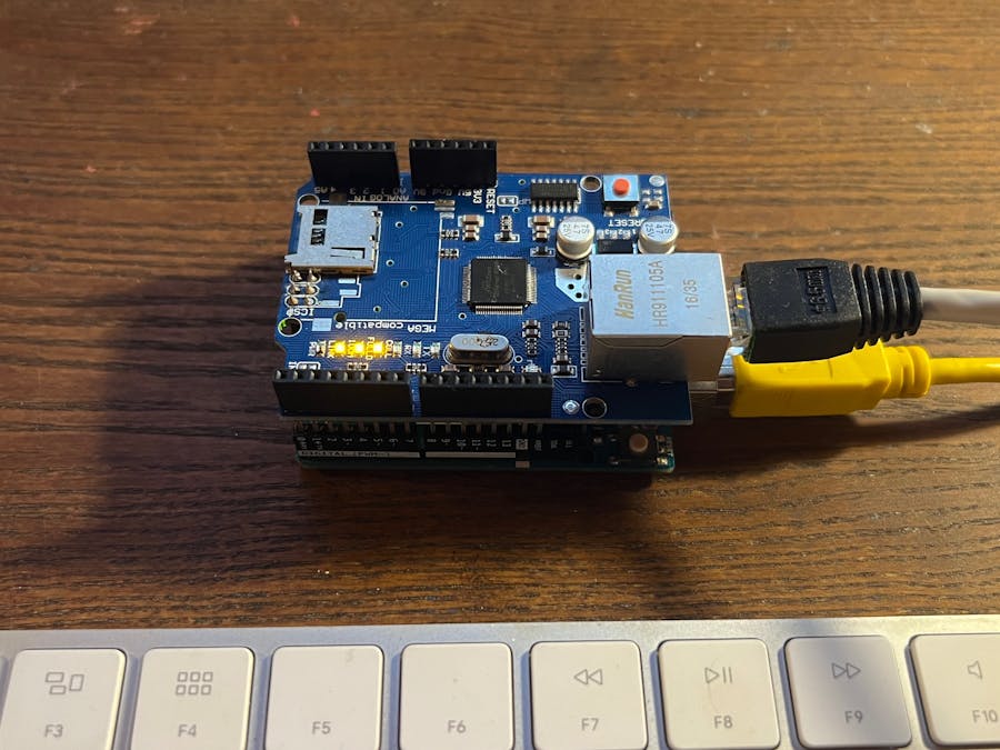
I started playing around with Arduino when I was eleven, my first project published on here (it suddenly disappeared now?) was when I was thirteen - but now I'm eighteen. Time has passed, but some days ago I decided to reopen the "Arduino box", and between burnt components and dead insects, I picked up my Arduino UNO and a Ethernet Shield knock-off bought on Aliexpress. I have to say that being this a "nostalgia project" I decided to buy nothing for this project and use only the items contained in that box - also, the Ethernet cable was for free because I stole it at school.
I decided to make a HomeKit related project because of two main reasons:
- I recently have bought a LED strip with a HomeKit compatible controller and it amazed me in a strange way I'm not gonna explain
- since all my digital devices (computer, phone, watch) are made by Apple, they all have the HomeKit native support
Being the Ethernet Shield not the most likely way to connect to an home automation accessory (Wi-Fi is preferred in most cases), there is not a "official and tested" way to connect directly to HomeKit without having something between. Instead, for the ESP-family, there is a library that makes the board directly accessible by HomeKit, and of course it is fairly more complex to configure and set up.
In this project, the communication between the Arduino board and HomeKit is managed by HomeBridge. HomeBridge is a server that can be hosted on a computer on a LAN and act as a "bridge" (as the name says) between the local network devices and the internet. This may be a downside because a computer hosting the server is needed, but it's more practical for a simple-coded device like the one we are gonna make.
In my case, this is not a device I will actually... use, it's more of a demo. So I hosted HomeBridge on my iMac. In this tutorial I'll not be showing you how to install it, but rather give to you a useful link that will show you the right way to do it, check this one out to install HomeBridge on macOS.
After that, you'll probably see something like so
After having installed HomeBridge, you have to add the so-called "HomeBridge Hub" to the Home app on your iPhone. To do so, follow these steps:
- open the Home app
- click on the "+" icon in the top right of the screen and click "Add accessory"
- scan the QR code shown on the HomeBridge dashboard
- click on "Add to Home"
- the app will say that the bridge it's not certified, add it anyways
- select the position of the bridge inside your home
- choose a name for the bridge
Having done so, the bridge will be added to your Home app
Installing the HomeBridge pluginsThe whole project relies on two plugins, the homebridge-http-rgb-push and the homebridge-http-notification-server. Fortunately for us, installing these plugins is very easy following these steps:
- go to the "Plugins" section fo HomeBridge
- type into the search bar the names of the two libraries
- install the libraries by clicking on the "install" button
Usually this process is very fast and it should not go wrong, if you are that lucky, we can proceed to the next step.
The HomeBridge configuration fileThe core of the HomeBridge configuration and customization is a JSON file. HomeBridge makes easy to access and modify it by loading it in a in-browser editor that can easily be accessed in the "Configuration" panel.
Here you have to make you first important decision, the IP address you want to set for your Arduino. You can always change it later, if you want. The configuration you most likely want to use for this accessory is the following.
Paste it inside the "accessories" brackets
{
     "accessory": "HttpPushRgb",
     "name": "Arduino RGB",
     "service": "Light",
     "timeout": 3000,
     "switch": {
         "notificationID": "47110815",
         "status": "http://192.168.1.177/statuspower",
         "powerOn": "http://192.168.1.177/on",
         "powerOff": "http://192.168.1.177/off"
      },
     "brightness": {
         "status": "http://192.168.1.177/statusbrightness",
         "url": "http://192.168.1.177/brightness/%s"
     },
     "color": {
         "status": "http://192.168.1.177/statuscolor",
         "url": "http://192.168.1.177/set/%s"
     }
 }
To set the accessory name, edit the "name" field. If you want to keep the IP address I used, there's no problem. At the end, you should see a screen like this one.
To apply these changes, you have to save the file by clicking the orange save button, then restart HomeBridge by clicking the shut-down icon in the top-right (it will start pulsing after having saved the file)
By opening the Home app, you now should see the accessory being automatically added.
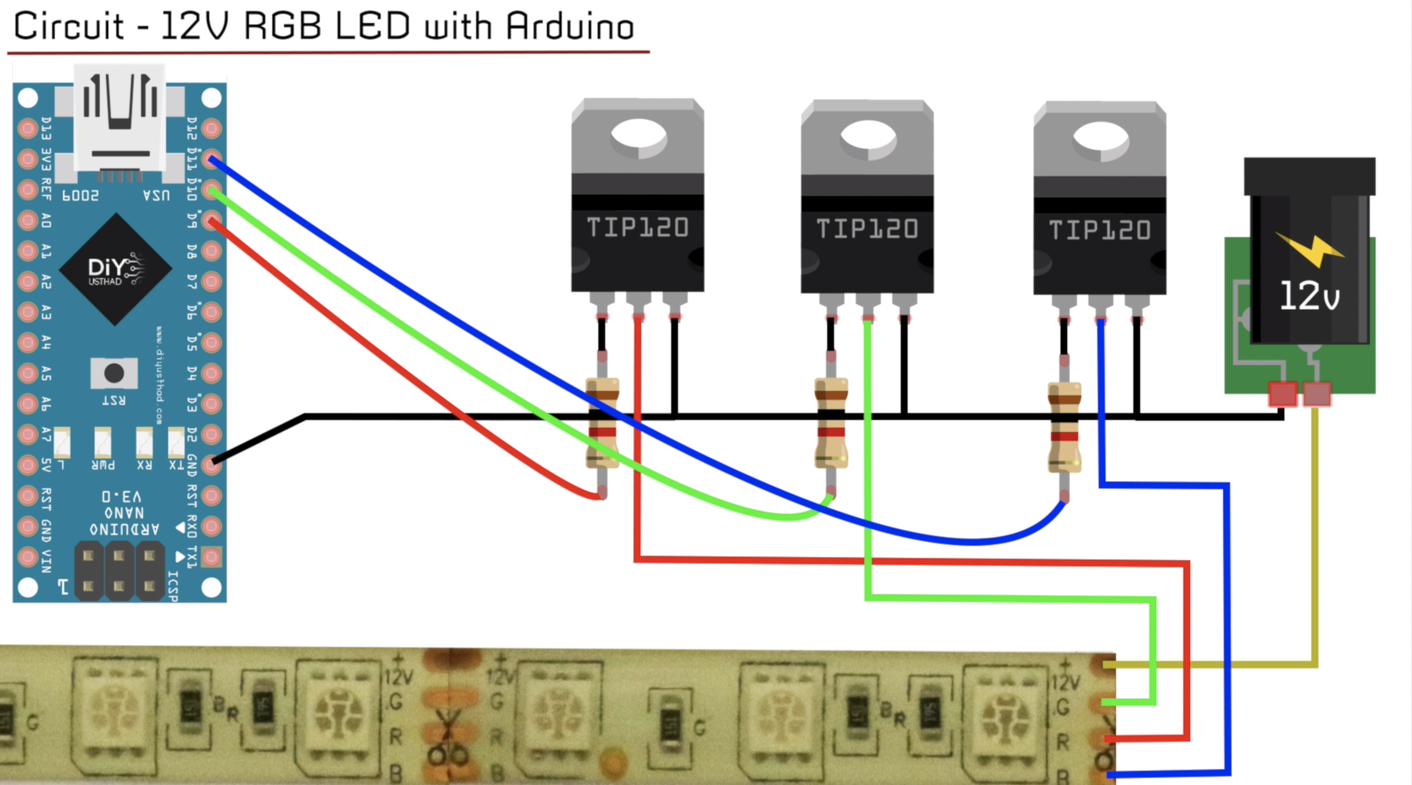
Yes, finally we are back on it. Also for the LED setup I used what I already had, this is what I used:
- a cheap and generic 12V LED strip
- some MOSFETS
- some 1k ohm resistors
- a 12V power adapter (previously used to power a broken router)
I followed this simple but complete tutorial, this is the scheme for the wiring
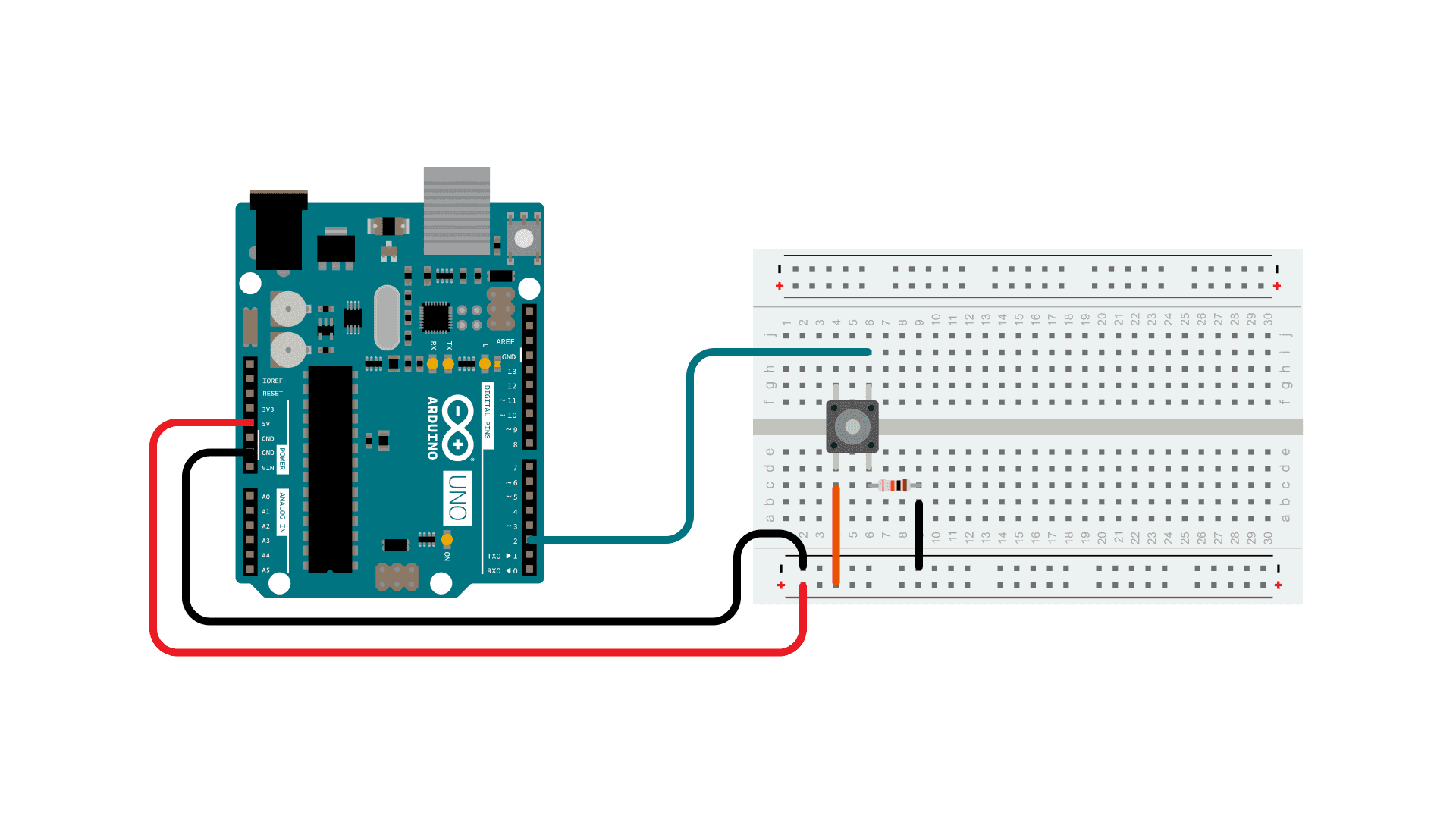
If you want, you can attach a simple push-button and use it as a "manual switch", this will also change the status on HomeKit by sending a notification to the server. Attaching a button shouldn't be that hard, but there's a good tutorial on how to do it :)
Speaking of code, it's not that complex. If you can't wait to test this out, you can directly upload it to your board without spending time watching at it. But stop! First you should check the defined pinout for the RGB channels and the button, then set the correct HomeBridge server IP address and the address chosen for your board.
// connections of the three LED outputs and the button input
#define outRed 3
#define outGreen 5
#define outBlue 6
#define switchButton 7
// network properties
char homebridgeServer[] = "xxx.xxx.xxx.xxx"; // your HomeBridge server IP address
int homebridgePort = 8581;
IPAddress ip(192, 168, 1, 177); // IP address of Arduino (must be equal to the one set on homebridge!)
The main address you want to focus on changing is the HomeBridge server address, this can be immediate to set if the machine where you host HomeBridge has a static IP address (a Pi, for example). In my case, my computer hasn't a static IP address inside the LAN, and I didn't want to set a static address just for this project. If you hare in the same situation as mine, you can use the .local mDNS address that most of the routers provide to every single host (in my case, the address I set was "myMacExample.local", the mDNS server of your router will automatically resolve this address and prompt the request to the right IP address).
You can always check your HomeBridge server address in the HomeBridge dashboard, right under the QR code image. If you plan to use HomeBridge on a daily basis, I really suggest you to assign a static IP address to the machine hosting it.
Last but not least, check that the Arduino's IP address set in the sketch is equal to the one set in the HomeBridge configuration file.
Having done all of that, you can now stick the Ethernet Shield onto Arduino, plug in the Ethernet cable and load the sketch.
Explaining the codeTo be sure to handle properly the Ethernet setup, I built my sketch starting from the official WebServer and WebClient examples. Making requests with the Arduino Ethernet library is rough, but easy.
This is the flow that is executed by the system when a change is made in the Home app:
- an event is sent by HomeKit to the HomeBridge server
- the HomeBridge server then sends it to the Arduino
- the Arduino makes it happen
- to confirm that the request has been satisfied, a response confirming it is required, so Arduino sends the confirmation to HomeBridge after performing the action
- then HomeBridge confirms that the action happened to HomeKit
- and finally HomeKit displays the change on the Home app
The code to handle the GET/SET of an action is the following. In this example the receiving-executing-confirming process of the "on" action is shown.
if (firstLine.indexOf("on") != -1) { // action is received
           Serial.println("Turning ON");
           // action is executed
           powerStatus = 1;
           analogWrite(outRed, colorR);
           analogWrite(outGreen, colorG);
           analogWrite(outBlue, colorB);
           // action in confirmed back to the server
           client.println("HTTP/1.1 200 OK");
           client.println("Content-Type: text/html");
           client.println("Connection: close");
           client.println();
           client.println(powerStatus);
}
To notify the server of a change of status, for example by a push-button that alters the state of the switch, the following flow is implemented
- Arduino sends a POST request to HomeBridge
- HomeBridge verifies the status of the device, verifying that matches the one sent by Arduino
- HomeBridge notifies HomeKit of the change of the status
- HomeKit shows the change on the Home app
This is the notification request build and sent by Arduino, the rest is done by HomeBridge
   Serial.println("==========");
   Serial.println("Button changed the state, sending a notification to HomeBridge");
   if (notificationClient.connect(homebridgeServer, homebridgePort)) {
     if (powerStatus == 0) {
       powerStatus = 1;
     } else {
       powerStatus = 0;
     }
     Serial.print("Successfully connected to: ");
     Serial.println(notificationClient.remoteIP());
     notificationClient.println("POST /47110815 HTTP/1.1");
     notificationClient.print("Host: ");
     notificationClient.print(homebridgeServer);
     notificationClient.print(":");
     notificationClient.println(homebridgePort);
     notificationClient.println("User-Agent: Arduino/1.0");
     if (powerStatus == 0) {
       notificationClient.println("Content-Length: 41");
     } else {
       notificationClient.println("Content-Length: 40");
     }
     notificationClient.println("Content-Type: application/json");
     notificationClient.println();
     if (powerStatus == 0) {
       notificationClient.println("{\"characteristic\": \"On\",\"value\": \"false\"}");
     } else {
       notificationClient.println("{\"characteristic\": \"On\",\"value\": \"true\"}");
     }
     delay(1);
     notificationClient.stop();
     Serial.println("Notification sent");
     Serial.println("==========");
   } else {
     Serial.println("Connection failed");
     Serial.println("==========");
   }
Having understood these flow concepts, the code come pretty easy to understand. It's made of basic HTTP requests, not that secure if you ask me, but HomeBridge will ensure security from internet connections.
...did it work?I really hope so! To be sure about that, always keep an eye on the serial monitor because very useful debug information will be logged there
On the serial monitor you will see every request that is received, complete of the action requested and the information processed. You will also see, when the button is triggered, the notification request being sent to the server
Also, always check the log on HomeBridge that shows every request is sent or received by the server
Yep, that's all. I hope this was easy to set up for you, as it wast hard for me to make it work. There are some problems I've encountered, for example the "loss" of the accessory on the Home app, probably caused by the non-continuous polling of HomeBridge towards Arduino. To gain again the control over the accessory just tap on it on the Home app, that will wake up HomeBridge and set back online the accessory.
I haven't tested this project in a long time span, thus I won't recommend relying on this kind of set up as a permanent solution to DIY home automation, there surely is better. But, hey, this was a chance of learning, both for me and (I hope!) for you, on how does this complicated thing - as HomeKit is - work.
For any problem, don't hesitate writing a comment. Down here there I'll leave some screenshots of the final look in the Home apps inside the Apple ecosystem.


Comments