

Hardware components | ||||||
_ztBMuBhMHo.jpg?auto=compress%2Cformat&w=48&h=48&fit=fill&bg=ffffff) |
| × | 1 | |||
| × | 1 | ||||
 |
| × | 1 | |||
 |
| × | 1 | |||
 |
| × | 1 | |||
I was looking for a easy way to connect an Arduino to a WiFi network and communicate data to another computer or device. An Ebay search returned the ESP13 shield from DOIT and for about $10 the shield arrived in my mail.
I was looking for an easy way to connect an Arduino to a WiFi network and communicate data to another computer or device. An Ebay search returned the ESP13shield from DOIT and for about $10 the shield arrived in my mail.
After researching the forums on the ESP13 Arduino shield from DOIT, it seems that board gets a bad rap and I was left wondering howto get it to work. I found the documentation from DOIT (search their website and you should find the document) and a post on the Arduino project hub by vectiva, which provided enough basic information to make a reasonable project. The bad reputation is probably a little exaggerated; I found the shield worked well.
Here are some important points I discovered about this shield:
- The particular shield and the instructions that follow is made by DOIT with propriety firmware and is not to be confused with similar boards made by Keyes. It is identified by the silkscreen DOIT logo and website near the dual dip switches (see photograph).
- It is a complete Arduino shield and fits exactly on the Arduino Uno. Other posts complain that the RX and TX lines from Arduino to the shield were swapped; my version did not have this problem and worked first time
- ESP13 refers to a specific model of the ESP8266 which has been incorporated in this shield. Its complete description is ‘ESP13: ESP8266 Remote Serial Wireless WIFI transceiver module AP+STA’. You can check out the specs on the ESP8266 community forums
- The shield has several useful features which, once understood, make it easy to use:
- It incorporates a 5V to 3.3V regulator which takes care of the different voltage requirements of the Arduino and ESP8266
- Digital pins 2 – 13 and Analog Pins 0 – 3 of the Arduino are available on the shield allowing easy connection to a range of Input/Output
- The ESP8266 GPIO pins are also available, should you want to connect directly to these
- The two dip switches allow the Arduino TX, RX to be disconnected from the shield so the Arduino can be programmed independently while the shield is in place.
- Should you wish to flash the ESP8266 with new firmware, all the connections and buttons are available – no need to build any external circuits
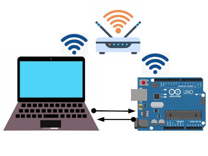
At a high level, the shield functions as a serial transmitter and receiver across a WiFi network. Once configured, the Arduino sends and receives information using the Serial.print() and Serial.readstring() functions to communicate with a remote host over a wireless network.
This project will show how a python program running on a laptop (or workstation) can read analog values from a potentiometer and control the brightness of a LED connected to an Arduino. High level steps as follows:
- Fit shield to Arduino and connect a LED and potentiometer
- Configure ESP13 module
- Run Python program on laptop
- Connect ESP13 to the Python program
- Use the program interface on your laptop to control the LED brightness and read the value of the analog input
Sockets are used in all networks to communicate data between devices. Although you may not be aware, every time you use a browser, a socket is buried in the stack facilitating that data transfer. They exist at the Session Layer of the OSI network model and most programming languages have libraries that allow for the creation and maintenance of sockets. The ESP13 WiFi shield connects via a socket and the computer or device communicating with the shield needs to create and maintain a socket for this interchange.
I used a Python 3 program and the associated socket library to facilitate communication between the ESP13 and the laptop. It is not the intention of this tutorial to provide instruction on socket programming. There are many resources on the internet that explain how they work and how they can be used in programs.
https://realpython.com/python-sockets/
https://docs.python.org/3/howto/sockets.html
However, it is worth noting that because a socket exists at the Session Layer of the OSI model, the program has to do all the functions above that level.
Arduino ConfigurationFit the shield to the Arduino as shown in the first photograph.Then go ahead and connect the devices to the shield as shown.
The pot can be any value from 5K upward. The series resistor with the LED can be 220ohms or 330 ohms. This connects the pot to A0 input and LED to digital output 3 of the Arduino.
Set the dip switch (1 and 2) to ‘OFF’
Upload the sketch included with this tutorial to the Arduino.Having the switches set to off disconnects the Arduino from the ESP13 shield and allows for the sketch download. Read the comments in the sketch to see how the program works.
 /*
 Arduino ESP13 Shield Program
 Once the ESP13 shield has connected to a WiFi Network, it sends data over the network from the Arduino that is
 written to the Serial lines. All data that the Arduino sends and recieves over the WiFi network uses the Serial.read, Serial.write
 and Serial.print commands.
 This program receives data from program running on a laptop using the socket connection.
 In order to distinguish between a simple receive / echo case and the LED brightness adjust, a arbitrary string "12#$" is transmitted
 as the four beginning bytes. If this is detected, then LED brightness is updated and pot value read from reply. (This string is totally
 arbitrary)
 If the header string is not present, then the arduino echos the the message sent.
*/
String incomingString;
String analogValue;
String headerString;
int ledPin = 3;
void setup() {
 // put your setup code here, to run once
 // Baud rate of ESP13 shield set up in configuration
 Serial.begin(115200);
}
void loop() {
 // reply only when you receive data:
 if (Serial.available() > 0)
 {
   // read the incoming string and strip out four first bytes:
   incomingString = Serial.readString();
   headerString = incomingString.substring(0,4);
   // If the header string equals "12#$" then update LED brightenss and pot value
   if (headerString.equals("12#$"))
   {
     //remove the first four bytes, analogWrite function needs and integer, conversion required
     incomingString.remove(0,4);
     analogWrite(ledPin,incomingString.toInt());
     //read the A0 analog input, convert to string and send back
     analogValue = String(analogRead(A0),DEC);
     Serial.print(analogValue);
   }
   else
   {
   // say what you got:
     Serial.print("ESPRecieved: ");
     Serial.flush();
     Serial.print(incomingString);
   }
 }
 else
 {
   delay(500);
 }
}
The ESP13 Module is configured via a webpage served from theESP3866. Use the following steps:
- Before starting, connect the laptop or computer to the wireless network you will be using to communicate with your Arduino. Then establish the IP address of your computer or laptop on this network (ipconfig in windows for example) and record this.
- Power Up the Arduino - this will provide power to the ESP13 shield.
- Disconnect your laptop or computer from the network used in Step1. Scan for available WiFi networks and you should see a network called DoitWiFi_Config. Connect to this network. It should have no password. If a password is required it will be 12345678.
- Open a browser and use the address http://192.168.4.1. This will bring up the ESP13 configuration page.
- Set Baud rate to 115200
- Use the Refresh button to scan for available WiFi networks and select from the AP List drop down the WiFi network you intend to use for communication. The grey boxes will fill automatically.
- Enter the network password
- Under NetWork Setting pick Client and TCP. Set remote port to 9000
- In remote IP enter the IP address you recorded in Step 1 of this section. This is the IP address of your laptop or computer on the WiFi network you will be communicating over
- Hit Submit. The ESP13 Shield will ask for an acknowledgment (Click OK) and the shield will reboot.
- The blue light on the shield will blink for a few seconds and then turn solid, indicating successful connection to your WiFi network. Leave the Arduino powered and connected.
- Now set the dip switches (1 and 2) to ‘ON’. This sets up serial communication between the Arduino and the ESP8266 on the shield. (Don't forget this step – the rest will not work otherwise)
You will need to have Python 3 installed on your laptop or computer. Refer to https://www.python.org/for downloads and install instructions, if you do not already have this installed.
Just a few points about the program:
- I am not a Python programmer, so don't criticize the code. Feel free to improve
- You will need the tkinter and socket libraries to run the program; if you get an error use PIP to install
- The program should run on Linux, Windows and Mac. I have tested it on Ubuntu Linux and Windows 7
- The program uses tkinter to create the graphical user interface (GUI). If you are interested in improving the interface, consult various internet resources on tkinter programming. (e.g. https://realpython.com/python-gui-tkinter/)
- Refer to comments in the program for general guidance on how the program works.
Launch the program from a terminal window in Linux. In Windows use a command prompt. If this does not work, refer to extensive docs on how to launch python programs.
Once the program launches, the following GUI should appear:
Follow the following steps carefully; the program does not have much error tolerance(because I can't program in Python).
- Click the “Initialize” button and the first entry dialog will read “Socket created Socket bind Complete”
- Click the “Connect” button and the second entry dialog will give a message “Connected with 192.168.1.XXX:XXXXX” or similar, depending on the IP address range of your WiFi network
- Congrats, your Arduino is now connected with your Laptop or Workstation over the WiFi network.
- You can now communicate with the Arduino via the GUI. Type in any message (up to 63 characters) in the “Message to send” entry dialog and hit the “Send” button. Your message will be echoed back.
- Adjust the “LED Brightness” slider bar and hit the “LED Update” button. The LED attached to your Arduino will update in brightness. Also, the “Analog Input” slider will update to reflect the setting of the potentiometer (between 0 and 1024).
The devices this program and sketch control and reads are rather simple. However, it can easily be extrapolated to more complex configurations of inputs and outputs. Once data from the Arduino is in a python program, much can be done with the values (logging, graphs etc.)


Comments