


Hardware components | ||||||
 |
| × | 1 | |||
 |
| × | 1 | |||
 |
| × | 1 | |||
| × | 1 | ||||
| × | 1 | ||||
| × | 1 | ||||
| × | 1 | ||||
| × | 1 | ||||
Software apps and online services | ||||||
 |
| |||||
There aren’t much content or beginner‑friendly tutorials available for the Ai-Thinker GP‑02 GNSSModule, even though it’s a compact and powerful receiver built around the AT6558R chip with a built‑in ceramic antenna. This guide aims to fill that gap by walking you step‑by‑step through how to connect and use the GP‑02 with a wide range of popular microcontrollers.
We’ll cover:
Seeed Studio XIAO ESP32S3Seeed Studio XIAO ESP32C3DFRobot FireBeetle 2 ESP32S3ESP32 DEV KIT V1(the most widely available ESP32 variant)
For each microcontroller, this guide provides:
- Proper pinouts for connecting the GP‑02 via UART.
- Example code snippets using the TinyGPSPlus library.
- Explanations of how the module receives satellite signals, parses them into NMEA sentences, and how the microcontroller reads and processes that data.
By the end, you’ll have a clear understanding of how to integrate the GP‑02 into your IoT or embedded projects, regardless of which ESP32 board you’re using.
📦 Device OverviewThe Ai-Thinker GP‑02 is a high‑performance BDS/GPS/GNSS multi‑mode satellite navigation receiver SoC module. It integrates:
- RF front‑end for capturing weak satellite signals.
- Digital baseband processor for demodulation and decoding.
- 32‑bit RISC CPU for positioning algorithms.
- Power management for efficient operation.
- Active antenna detection and protection for reliability.
- Built‑in ceramic antenna for compact design and simplified deployment.
It supports multiple satellite navigation systems:
- BDS (BeiDou) – China
- GPS – United States
- GLONASS – Russia
This multi‑system joint positioning improves accuracy and robustness.The GP‑02 communicates using the industry‑standard NMEA protocol, outputting data such as latitude, longitude, altitude, speed, and satellite information in simple ASCII text sentences (e.g., $GPRMC, $GPGGA). Because NMEA is universally supported, the module can be connected to any microcontroller via a UART interface (TX/RX pins).
- Satellites orbit Earth and broadcast signals in the L‑band.
- Each signal contains: precise timing information, orbital data (ephemeris), and satellite ID codes.
- The receiver measures the time delay to calculate distance.
- With signals from at least 4 satellites, the module computes latitude, longitude, altitude, and clock offset.
- Signal Reception: RF front‑end amplifies and filters satellite signals.
- Baseband Processing: Correlates signals with satellite codes, extracts navigation data.
- CPU Computation: Runs trilateration algorithms to determine position.
- Output: Provides standard NMEA sentences (e.g.,
$GPRMC,$GPGGA) via UART.
The GP‑02 communicates with microcontrollers (ESP32, Arduino) via UART serial.
- TX (Transmit): GP‑02 sends NMEA sentences containing GPS data.
- RX (Receive): GP‑02 listens to the microcontroller, which can send configuration commands back to the module.
The microcontroller reads the data stream from the GP‑02 and parses it using libraries such as TinyGPSPlus.
🛠️ PrerequisitesHardware- GP‑02 module
If you are from India, you can purchase the GP‑02 GNSS module from below websites:
Ai-Thinker GP-02 Precision GPS/GNSS Module - techiesms
Ai-Thinker GP-02 Kit GPS Development Board BDS/GNSS/GPS Module – REES52
- One of the supported microcontrollers:
Seeed Studio XIAO ESP32S3
Seeed Studio XIAO ESP32C3
DFRobot FireBeetle 2 ESP32S3
ESP32 DEV KIT V1
- OLED display (SSD1306 or SH1106, I²C interface)
- Jumper wires and breadboard
Software- Arduino IDE (latest version)
- ESP32 board support installed via Arduino Boards Manager
Libraries:- TinyGPSPlus (for parsing NMEA sentences)
- Adafruit SSD1306 (for OLED Display)
In the Arduino IDE, navigate to Library Manager window and install the following libraries:
TinyGPSPlus
Adafruit SSD1306
Using the images below, connect your microcontroller (MCU) with the GP‑02 module and the OLED display using jumper wires.
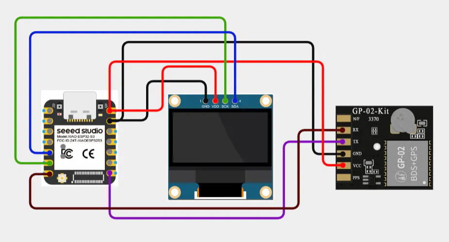
1. Seeed Studio XIAO ESP32S3
- GNSS module TX → XIAO RX D7
- GNSS module RX → XIAO TX D6
- GNSS module VCC → 5V
- GNSS module GND → GND
- OLED SDA → XIAO SDA
- OLED SCL → XIAO SCL
- OLED VCC → 5V
- OLED GND → GND
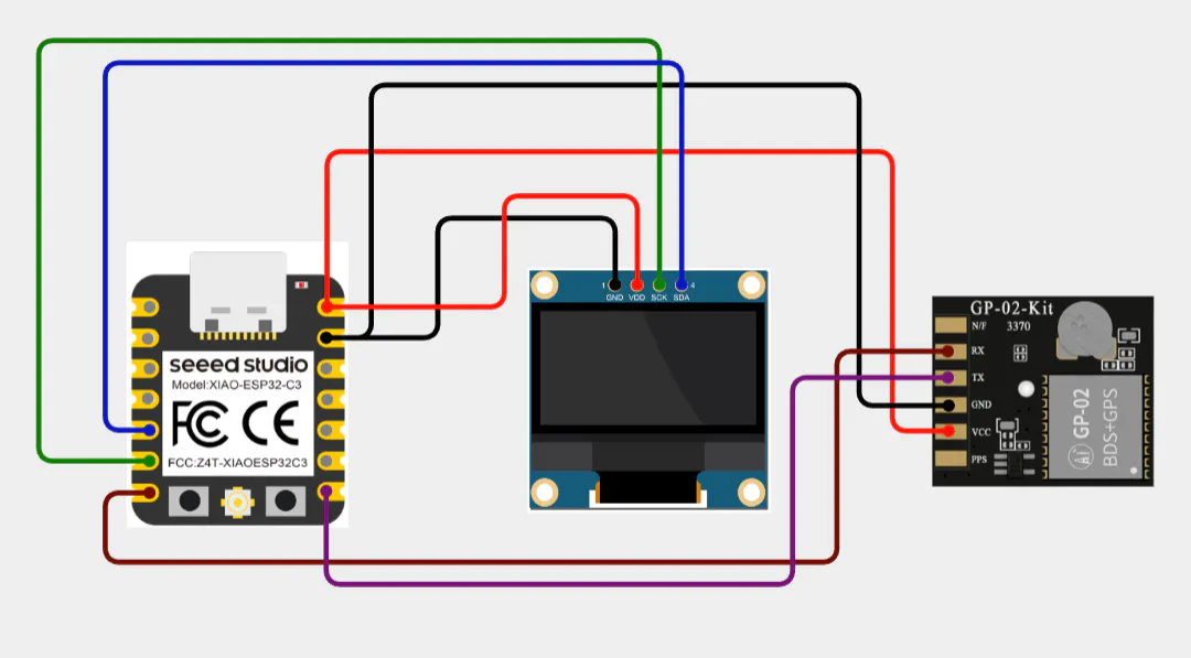
2. Seeed Studio XIAO ESP32C3
- GNSS module TX → XIAO RX D7
- GNSS module RX → XIAO TX D6
- GNSS module VCC → 5V
- GNSS module GND → GND
- OLED SDA → XIAO SDA
- OLED SCL → XIAO SCL
- OLED VCC → 5V
- OLED GND → GND
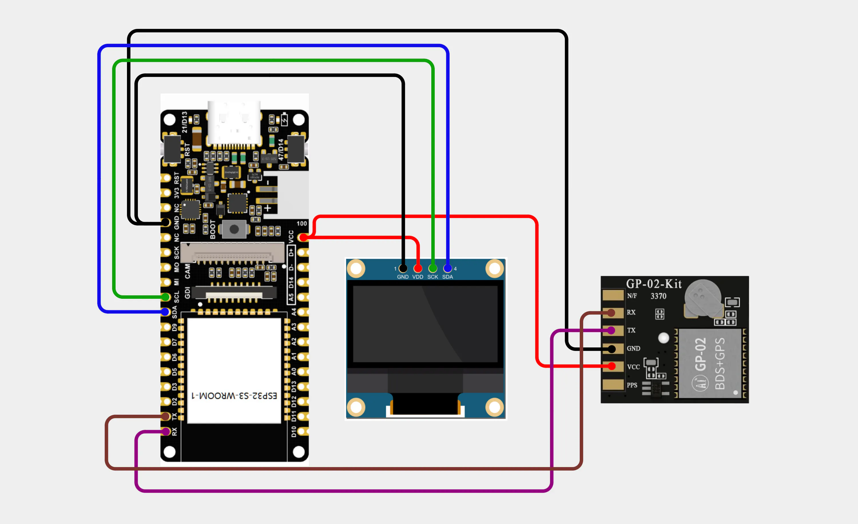
3. DFRobot FireBeetle 2 ESP32S3
- GNSS module TX → FireBeetle RX GPIO44
- GNSS module RX → FireBeetle TX GPIO43
- GNSS module VCC → 5v
- GNSS module GND → GND
- OLED SDA → FireBeetle SDA
- OLED SCL → FireBeetle SCL
- OLED VCC → 5V
- OLED GND → GND
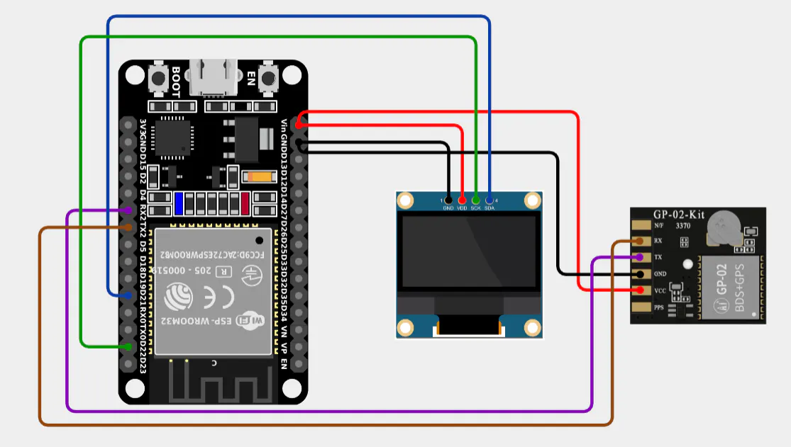
4. ESP32 DEV KIT V1
- GNSS module TX → ESP32 RX GPIO16
- GNSS module RX → ESP32 TX GPIO17
- GNSS module VCC → 5v
- GNSS module GND → GND
- OLED SDA → ESP32 GPIO21 (default SDA)
- OLED SCL → ESP32 GPIO22 (default SCL)
- OLED VCC → 5V
- OLED GND → GND
Each board has its own method of uploading code, so make sure to pay close attention to the instructions specific to your microcontroller. The upload process may vary slightly depending on the board drivers, USB connection, or IDE settings.
Note: Before we begin uploading the main code, connect only the OLED display to your microcontroller (do not connect the GNSS module yet). Run the WireScan sketch provided below — this will detect the I²C address of your OLED display.
- My OLED address is 0x3C.
- Please update the I²C address in the upcoming microcontroller codes according to the value you find.
#include "Wire.h"

void setup() {
    Serial.begin(115200);
    Wire.begin();
}
void loop() {
    byte error, address;
    int nDevices = 0;
    delay(5000);

    Serial.println("Scanning for I2C devices ...");
    for (address = 0x01; address < 0x7f; address++) {
        Wire.beginTransmission(address);
        error = Wire.endTransmission();
        if (error == 0) {
            Serial.printf("I2C device found at address 0x%02X\n", address);
            nDevices++;
        } else if (error != 2) {
          Serial.printf("Error %d at address 0x%02X\n", error, address);
        }
    }
    if (nDevices == 0) {
        Serial.println("No I2C devices found");
    }
}
Whether you are running the WireScan sketch or the upcoming GNSS code, always follow the Arduino IDE upload instructions shown in the image for your specific board.
1. Seeed Studio XIAO ESP32S3
Follow the instructions from the images below:
2. Seeed Studio XIAO ESP32C3
Follow the same steps as for the Seeed Studio XIAO ESP32S3, but be sure to select the correct board as shown in the image. Also, don’t forget to choose the right COM port in the Arduino IDE (Tools → Port) that matches your connected board. All other settings remain unchanged.
3. DFRobot FireBeetle 2 ESP32S3
Follow the instructions from the images below:
4. ESP32 DEV KIT V1
Follow the same steps as for the Seeed Studio XIAO ESP32S3, but be sure to select the correct board as shown in the image. Also, don’t forget to choose the right COM port in the Arduino IDE (Tools → Port) that matches your connected board. All other settings remain unchanged.
Now that we’ve gone through the step‑by‑step images showing how to upload code using the Arduino IDE, it’s time to move on to the individual microcontroller codes for the GP‑02 module.
Please refer back to the images for the correct upload instructions (board selection, port number, and upload method) when flashing the codes into your respective microcontroller. The process remains the same — only the code changes depending on the board you are using.
👉 The complete codes for each individual board have been attached below this guide in the Code section.
💡 Important Note (Line 11 of the code)
#define ADDRESS 0x3C // Replace this with the I2C address of your OLED displayPlease replace 0x3C with the I2C address obtained from the WireScan sketch (shown earlier in the Serial Monitor). This ensures the code communicates correctly with your specific OLED display!
For reliable GPS/GNSS reception, the ceramic antenna must face the sky.(It can work indoors as well, but signals are weaker and the fix takes more time compared to outdoors testing. For best results, test outdoors first.)
I live in an apartment building with 5 floors overall, and even indoors I was able to get a fix when I placed the setup near a window.
📷 I am attaching the image below to illustrate the setup.
🖥️ OLED Display Status Messages
When running the code, the OLED will show different messages depending on whether the GPS module is detected:
- “Waiting for GPS” → The system is powered and waiting to receive valid serial data from the GNSS module.
- “No GPS detected!” (after ~5 seconds) → No valid data was received.
🔧 Troubleshooting
- If you see “No GPS detected!”, first recheck the wiring connections between your microcontroller and the GNSS module.
- If wiring is correct and the error persists, it likely means the GPS module is damaged or not functioning properly.
📷 I am attaching the images below to illustrate both display states.
🖥️ OLED When GNSS Module is Working
Once the GNSS module begins receiving valid satellite data, the OLED display will start showing:
- Latitude(initially invalid during cold or hot start)
- Longitude(initially invalid during cold or hot start)
- Number of satellites connected(shows 0 until a fix is achieved)
- Altitude(shows 0 until a fix is achieved)
- Speed(shows 0 until movement is detected after a fix)
- Course (shows 0 until movement is detected after a fix)
- UTC Time
- Date
⚠️ Important Notes:
- During a cold start (first power‑on), UTC time and date might appear incorrect until a proper fix is achieved.
- During a hot start (resume after recent satellite lock):(faster reacquisition since satellite data is already cached) — even if latitude, longitude, satellites, altitude, speed, or course are not yet available, the date and UTC time are cached and will display correctly.
📷 I am attaching the image below.
🛰️ OLED When Satellite Lock/Fix
Once the GNSS module achieves a satellite lock (fix), the OLED display will update with valid positioning data:
- Latitude & Longitude → Now correctly received and displayed.
- Number of Satellites → Updated from 0 to the actual count of satellites connected.
- Altitude → Updated from 0 to the measured altitude.
- Speed → Updated from 0 to the current movement speed.
- Course (direction of movement) → Updated from 0 to the actual course.
- UTC Time → Corrected if previously wrong during cold start.
- Date → Corrected if previously wrong during cold start.
⚡ Key Point:After satellite lock, all values that were previously invalid or showing as 0 will be updated with real data. This is the stage where your GNSS module confirms it is working properly.
📷 I am attaching the image below.
🎮 Microcontroller Setups (Image Reference)
From the datasheet, here are the key performance parameters of the Ai‑Thinker GP‑02 GNSS module:
- Cold Start vs Hot Start: Cold start means the module has no prior satellite data; hot start uses cached data, hence much faster.
- Accuracy: <2 m positioning accuracy is sufficient for most IoT and navigation projects.
- Update Rate: Default is 1 Hz, but can be configured up to 5 Hz for faster tracking.
- Timing Accuracy: <30 ns makes it suitable for synchronization tasks in communication systems.
In this guide, we explored the GP‑02 GNSS module integration with multiple microcontrollers, step‑by‑step upload instructions, OLED display behaviour, antenna positioning, and troubleshooting methods.
🌍 Real‑World Performance
Although the datasheet specifies typical cold start and hot start timings, in practice I observed:
- Cold Start: ~40 seconds
- Hot Start: ~7 seconds
These timings can vary depending on factors such as:
- Location and surrounding environment (urban vs open sky)
- Weather conditions
- Satellite positioning and visibility
- Antenna placement and orientation
- Electromagnetic interference nearby
Despite these variations, the module consistently delivers:
- Positioning accuracy of less than 2 m, as claimed in the datasheet — locations are shown perfectly.
- Speed readings that are highly accurate and precise.
📌 Final Note
The more satellites the module connects to, the better and more reliable the data received — ensuring improved accuracy for position, speed, and timing.


Comments