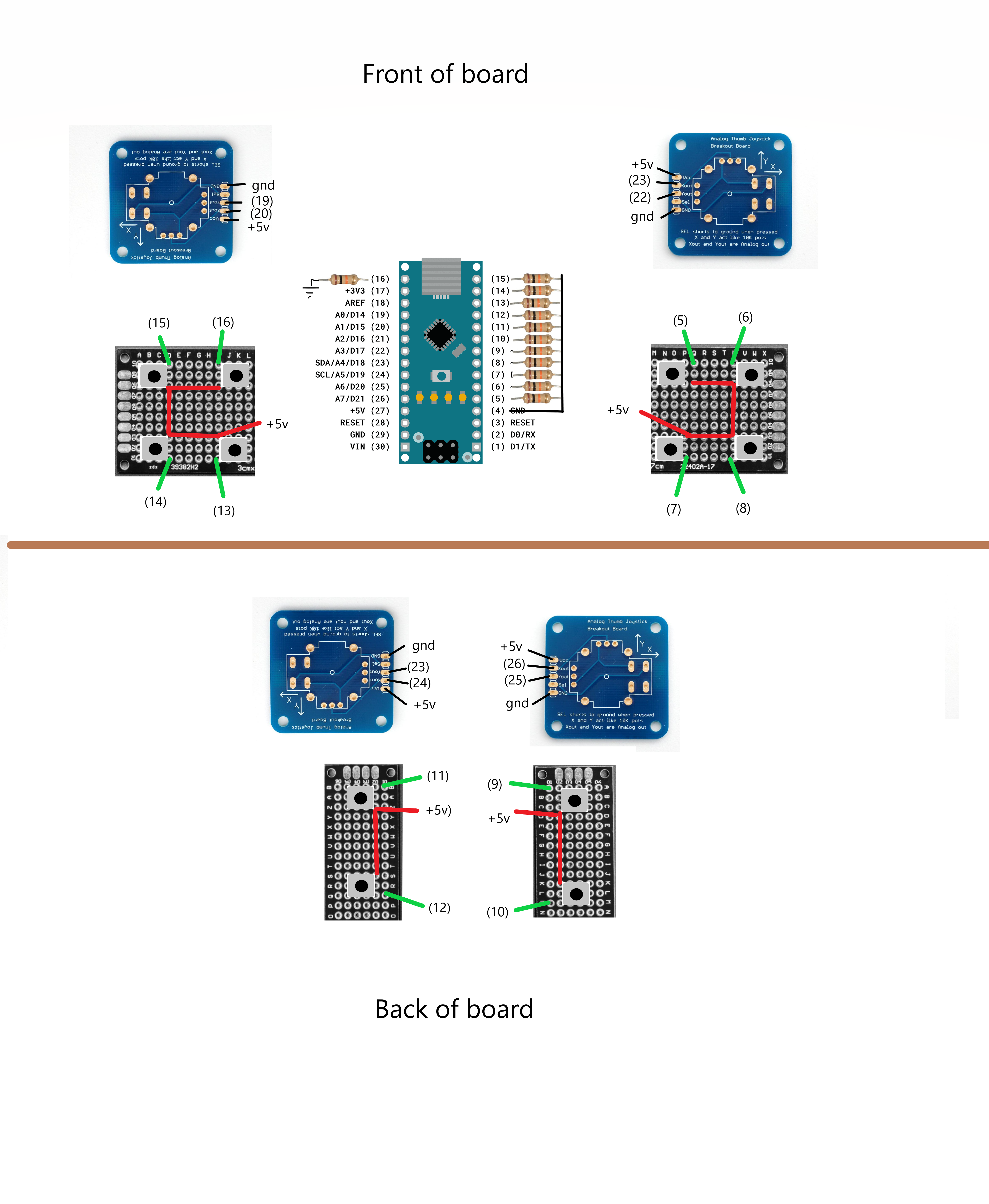
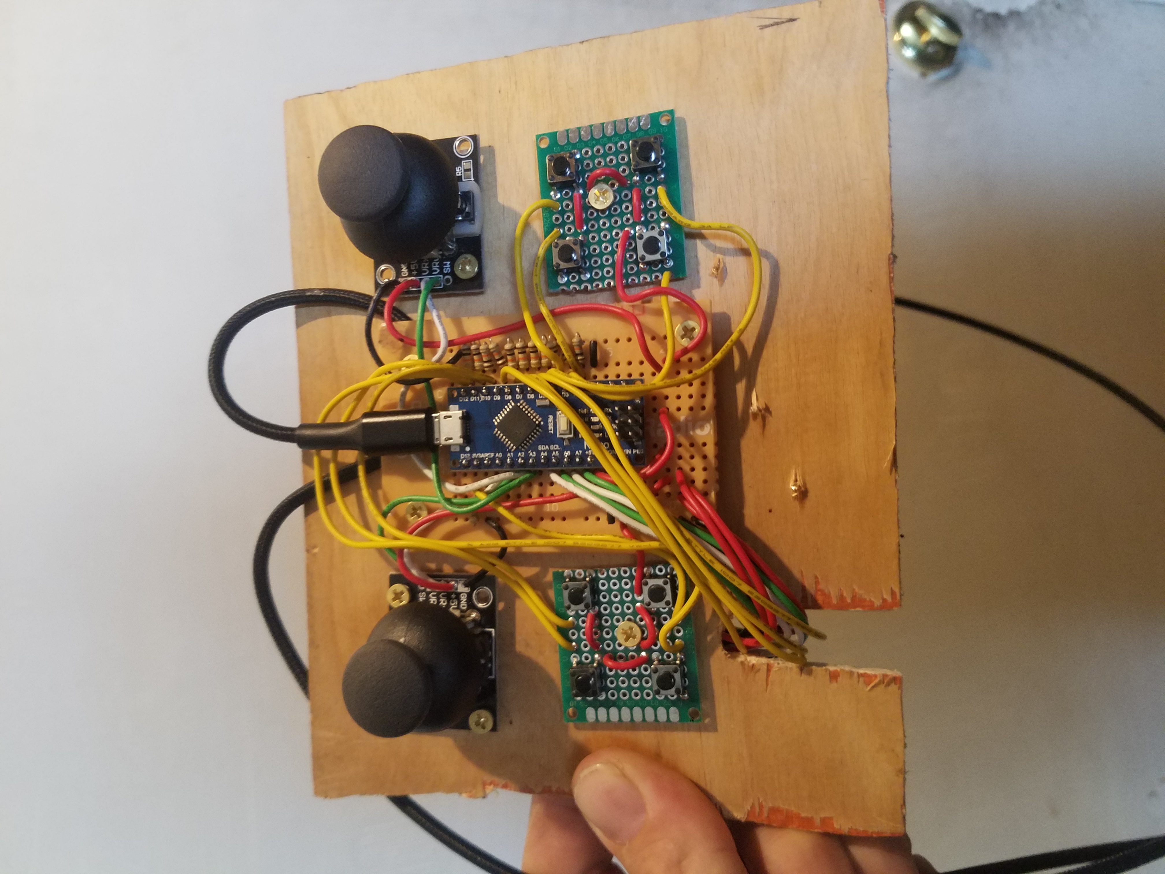
My project is designed to make casual 6 axis space navigation a possibility. On a normal gamepad 6 axis would require the use of buttons in unusual places, and the only two other options for 6 axis gaming are some assortment of buttons on the keyboard that require your more fingers than you have, or a complex set of joysticks that are difficult to use casually with your feet up. I decided to make this project after loving FPV, but not the simulator, and wishing that the same experience were available in a space game. The controller uses a "driver" that is available on github, and the sketch that is posted with it. I don't know this creator, but it's a full-featured very powerful app initially aimed at using rc controllers on pc.
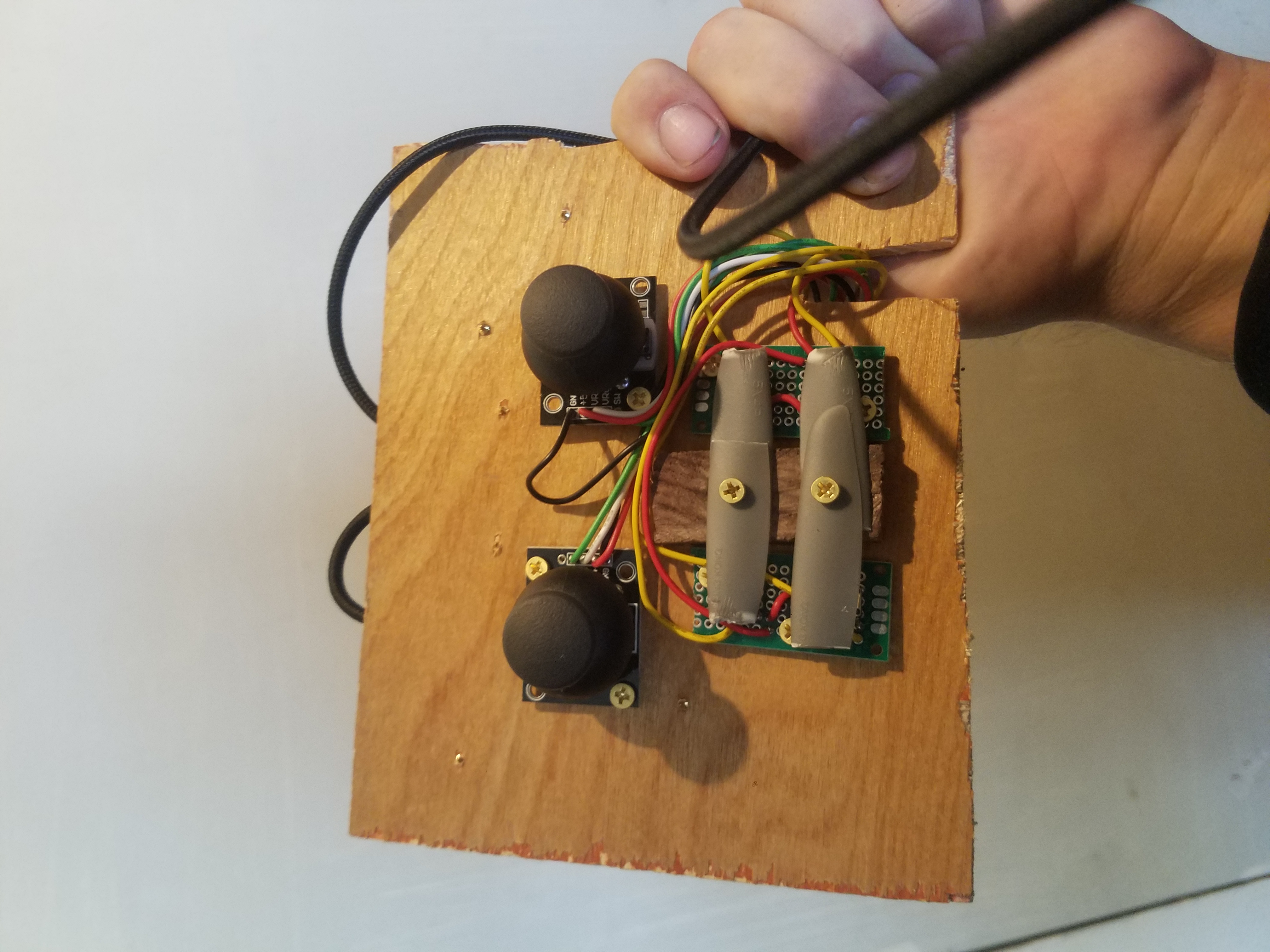
You can use a hacksaw to cut the prototyping board. Use a clamp to hold it to a table if you aren't able to grip the prototyping board itself, but you can just hold it. I used regular solid-core wire and through-hole components because it's easy to assemble and troubleshoot. Also, the solid core wire doesn't flop around, so you can use extra long wires to make it easy to assemble and troubleshoot, and then they will stay put once you put everything back together. I simply used a thin 3/16 plywood board as my chassis, and some #4 1/2inch screws to mount the modules to the board. It's great to have the modular design so that you can play around with the specific locations of the components. if plywood is uncomfortable for your hands, you can use some finish or paint on the board before you mount the modules. Instead of drilling a hole to run the wires through, I recommend a cutaway that runs from the bottom of the board up about an inch or an inch and a half, and to one side of the buttons on the underside of the board, not the center, that way while assembling or troubleshooting, you can easily remove the entire electronics from the board without disconnecting the wires to the rear components. I used the center to mount some levers to make it easier to press the buttons on the underside, as you can see in the images, because it's hard to push the buttons quickly when you are just pushing the buttons directly with your ring finger.
IMPORTANT::::: the usb connector on the arduino cannot handle the weight of the wire over time, and the connection will fail over time unless the weight of the cable is supported and the connector is inserted and removed as rarely as possible. My solution as pictured was to use one of the mounting screws and the corner of the pcb holding the nano to clamp the wire in place, and then to simply leave the wire always plugged in unless shipping or otherwise risking impact to the plug. The USB a is a full size connector that is able to withstand frequent unplugging and tension, so I recommend always plugging and unplugging via the USB-A end of your cable. I am using a usb extender to get extra reach and keep my pc usb connector from constant wear and tear. It would be easy to mount a wire permanently using the arduino's tx,rx,vin,and ground, but but often the wires in these cables are not durable over time once exposed, so I recommend simply using the usb connector on the arduino, and exercising caution with the plug.
My favorite games to play with the controller are: Orbital Racer, Infinity Battlescape, Starmade, and Absolute Territory (which runs well on low performance budget computers!). Start with Orbital Racer, and visit my hackaday page here for a Starmade world download filled with navigation courses. (Starmade has a free demo! and it's the full version of the game!)
https://hackaday.io/project/180884-4-joystick-6-axis-6-dof-game-controller
My recommended configuration for beginners (it's not hard I promise!!! If you can use a normal 2joy gamepad, this will feel almost the same, and within a single sitdown you should start to come to grips!) only uses 6 axis, but uses all 4 joysticks. This is to give your pointer fingers time to train up on joystick use! You can be extra sloppy but still have a perfectly game-able performance!! Assignments as follows:
- left thumb: accelerate up down left right
-right thumb: pitch yaw
-left finger: accelerate forward reverse (pull trigger for forward, push trigger away for reverse!)
-right finger: roll
over time, as your skills improve, you can move the roll over to your throttle finger (left finger), and place the camera tilt on the right finger. This will allow you to see your angles or control a turret with one joystick, while all flight controls are on the other 3. It's possible to start right away with it, but as of the time of this publication, orbital racer did not support joystick camera angles, and I recommend learning coordination gradually but with more success, rather than struggling with roll and never completing a race!! Infinity Battlescape already supports the 8 axis option, and I'm always excited for future game releases!
Here are some videos


Comments