

Hardware components | ||||||
 |
| × | 4 | |||
|
| × | 1 | |||
|
| × | 1 | |||
 |
| × | 1 | |||
 |
| × | 1 | |||
 |
| × | 1 | |||
Software apps and online services | ||||||
| ||||||
Hand tools and fabrication machines | ||||||
 |
| |||||
## A $25 ESP32 Robot Arm Rover for Kids Learning Robotics
A lot of robot arm kits are cool, but they can get expensive fast. This project keeps the parts list small and cheap: an ESP32 DevKit, three MG996 servos, four SG90 servos, and a simple battery setup. The goal is a rover with a 5-DOF arm that can be controlled from any phone or laptop without installing an app.
When the ESP32 turns on, it creates its own Wi-Fi network called `ESP32-Robot-Arm`. There is no password, so a student can connect directly, open `http://192.168.4.1`, and start driving. The web page has a joystick for the rover drivetrain and another joystick for the arm. There are also sliders for the arm servos, including direct PWM control for testing and calibration.
The best part for learning is the "Program Your Robot" mode. It works like simple block coding. Kids can add a drivetrain block to move a motor for a selected amount of time, or add an arm block to move one servo to an angle. Then they press Go and the robot follows the sequence. It is not meant to be a complicated industrial robot controller. It is meant to make the idea of robotics feel reachable.
## What It Uses
The robot uses seven servo outputs. Two MG996 servos drive the left and right drivetrain. One MG996 servo is used for the heavier arm joint, and four SG90 servos handle the other arm joints. The ESP32 controls all of them using PWM. The web interface is served directly by the ESP32, so there is no router, cloud account, or phone app required.
The estimated cost is around $25. The rough BOM is:
- 3x MG996 servos, about $9 total
- 4x SG90 servos, about $4 total
- ESP32 DevKit, about $3
- Old 2-cell 3.7 V battery pack in series, reused if available
- Or 1x 18650 cell plus TP4056 charger module, about $4 total
- 6 V boost converter for the servos, about $1
- M3 screws and nuts
- M2 screws for tapping the SG90 servo horns
- 608 bearings for the front wheel and arm base support
- 3D printed robot base, arm parts, wheel axis rod, covers, servo holders, and claw
## Mechanical Build
Start with the drivetrain before building the arm. Flip the 3D printed robot base upside down and mount the two MG996 drivetrain servos on the back sides of the robot. Use M3 screws and nuts to hold the MG996 motors firmly in place. These two servos are the left and right drive motors.
For the front wheel, place a 608 bearing into the bearing slot at the front of the robot base. Slide the 3D printed wheel axis rod through the bearing hole, then add the second 608 bearing on the other side. Attach the bearing cover, which also works as the front wheel. This makes the robot drive like a small auto rickshaw: two powered rear wheels and one supported front wheel.
Before attaching the arm, prepare the servo horns. Use M2 screws to tap the SG90 servo horns. Use M3 screws to lock the MG996 servo horns. This makes the joints stronger and helps keep the arm from slipping while it moves.
Now build the arm base. Use M3 screws to mount the arm base to the robot. Mount the base yaw servo into the yaw mount. If your printed design uses an MG90-size yaw servo, install the MG90 there. If your version uses the same parts as the firmware BOM, use the MG996-size yaw servo mount. After mounting the cover, add two 608 bearings so the base can rotate with support instead of relying only on the servo.
Next mount the MG996 base pitch servo. This servo handles the heavier pitch axis of the arm. Add the bearing on its matching side so the MG996 rotation axis is supported from both sides. After the pitch servo and bearing are installed, attach the first arm section to the MG996 horn and supported bearing side.
Attach the first SG90 servo to that arm section. Then attach the next arm section to the SG90 servo horn. On that next arm section, install another SG90 servo into the provided slot. Attach the SG90 holder to that servo. From the SG90 holder, mount the claw SG90 servo, and finally attach the claw to the claw servo.
The arm should now have a base yaw joint, a base pitch joint, two arm joints, and a claw joint. Move everything gently by hand before powering it to make sure nothing binds.
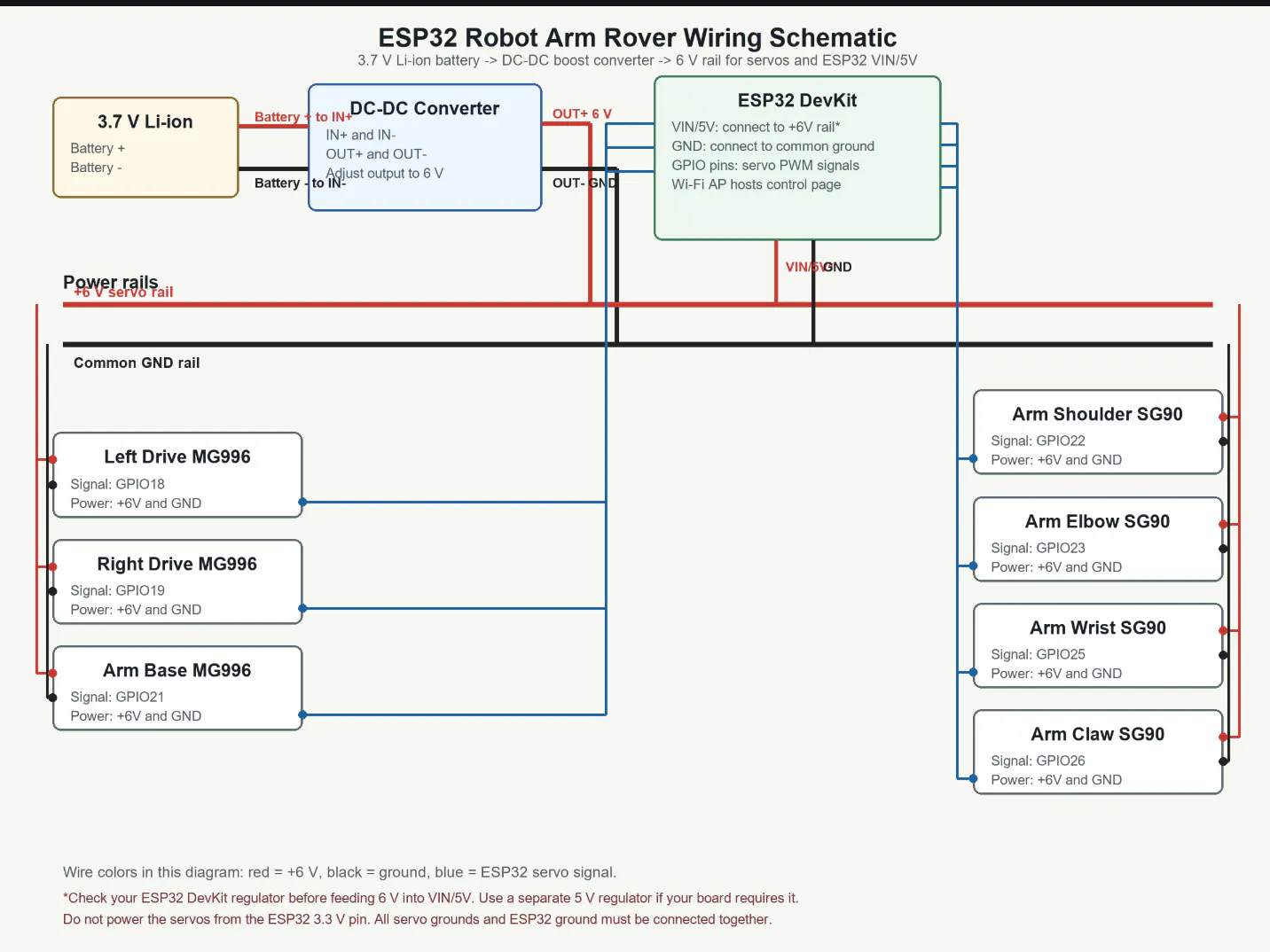
## Wiring
Use double-sided tape to place the ESP32 backwards in the center of the robot base. Put the battery and TP4056 charger module on the side of the robot where they fit best. Connect the battery output to the boost converter input, then adjust or use the converter output as the 6 V rail for the servos.
The important wiring rule is common ground. The servo power supply ground, boost converter ground, battery ground, and ESP32 ground must all connect together.
Use the GPIO wiring from the firmware:
- Left drivetrain MG996 signal: GPIO18
- Right drivetrain MG996 signal: GPIO19
- Arm base / heavy joint MG996 signal: GPIO21
- Arm shoulder SG90 signal: GPIO22
- Arm elbow SG90 signal: GPIO23
- Arm wrist SG90 signal: GPIO25
- Arm claw SG90 signal: GPIO26
Connect the red servo wires to the 6 V boost converter output. Connect the brown or black servo wires to ground. Connect the orange, yellow, or white servo signal wires to the matching ESP32 GPIO pins.
Do not power the servos from the ESP32 3.3 V pin. Servos pull a lot of current, especially MG996 servos. Use the boost converter for servo power, and use adult supervision when charging or wiring lithium batteries.
## Flashing the ESP32
The repo includes prebuilt firmware binaries in the `firmware/` folder:
- `bootloader.bin`
- `partition-table.bin`
- `esp32_robot_arm.bin`
To flash with `esptool`, plug in the ESP32 and replace `COM4` with your ESP32 port:
```powershell
python -m esptool --chip esp32 -p COM4 -b 460800 --before default-reset --after hard-reset write-flash --flash-mode dio --flash-size 2MB --flash-freq 40m 0x1000 firmware/bootloader.bin 0x8000 firmware/partition-table.bin 0x10000 firmware/esp32_robot_arm.bin
```
You can also build and flash from ESP-IDF:
```powershell
idf.py set-target esp32
idf.py build
idf.py -p COM4 flash
```
## Using It
After flashing, power the robot and wait for the ESP32 to start its Wi-Fi access point.
Connect to:
```text
ESP32-Robot-Arm
```
There is no password. Then open:
```text
http://192.168.4.1
```
Use the left joystick to drive the rover. Use the arm controls to move each servo. In "Program Your Robot" mode, add drive blocks and servo blocks, then press Go to run the sequence.
The design is intentionally flexible. The frame can be made from cardboard, laser-cut wood, 3D printed parts, or whatever a classroom already has. That is part of the learning: the robot is cheap enough that students can change it, improve it, and make mistakes without being scared of ruining an expensive kit.
This project is open source under the MIT License. My hope is that teachers, parents, makerspaces, and students can use it as a starting point for a very low-cost robotics lesson: drive a rover, move an arm, learn PWM, learn Wi-Fi control, and then start changing the code.
It is small, cheap, and simple on purpose. That makes it a good first robot.

_t9PF3orMPd.png?auto=compress%2Cformat&w=40&h=40&fit=fillmax&bg=fff&dpr=2)


Comments