

Hardware components | ||||||
 |
| × | 1 | |||
 |
| × | 1 | |||
Software apps and online services | ||||||
| ||||||
The Autonomous Garden Management System, or GMS, is my in-progress autonomous garden maintenance rover. The goal is to build a practical low-cost outdoor robot that can mow, water plants, aim a hose, and eventually support modular garden tools.
## Current ProgressThe project is currently in progress.
Completed or mostly complete:
- Drivetrain mechanical build
- Front mower module
- Rope-based mower lift mechanism
- FOC mower motor controller wiring
- Front section of the robot
- Worm-gear rotating turret base for the first hose turret degree of freedom
In progress:
- Rear section of the robot
- 2-DOF hose turret
- Second hose turret axis for up/down hose angle
- Base-station hose attachment interface
- ESP32-P4 high-level control software
- STM32 F103 low-level control firmware
- Control box layout
- Wiring documentation
- Test procedures
Planned:
- Autonomous hose attach/detach at the base station
- Plant-targeted watering
- Controlled liquid application module, tested with water first
- Outdoor navigation and obstacle handling
- Field test logs
- Final BOM and cost documentation
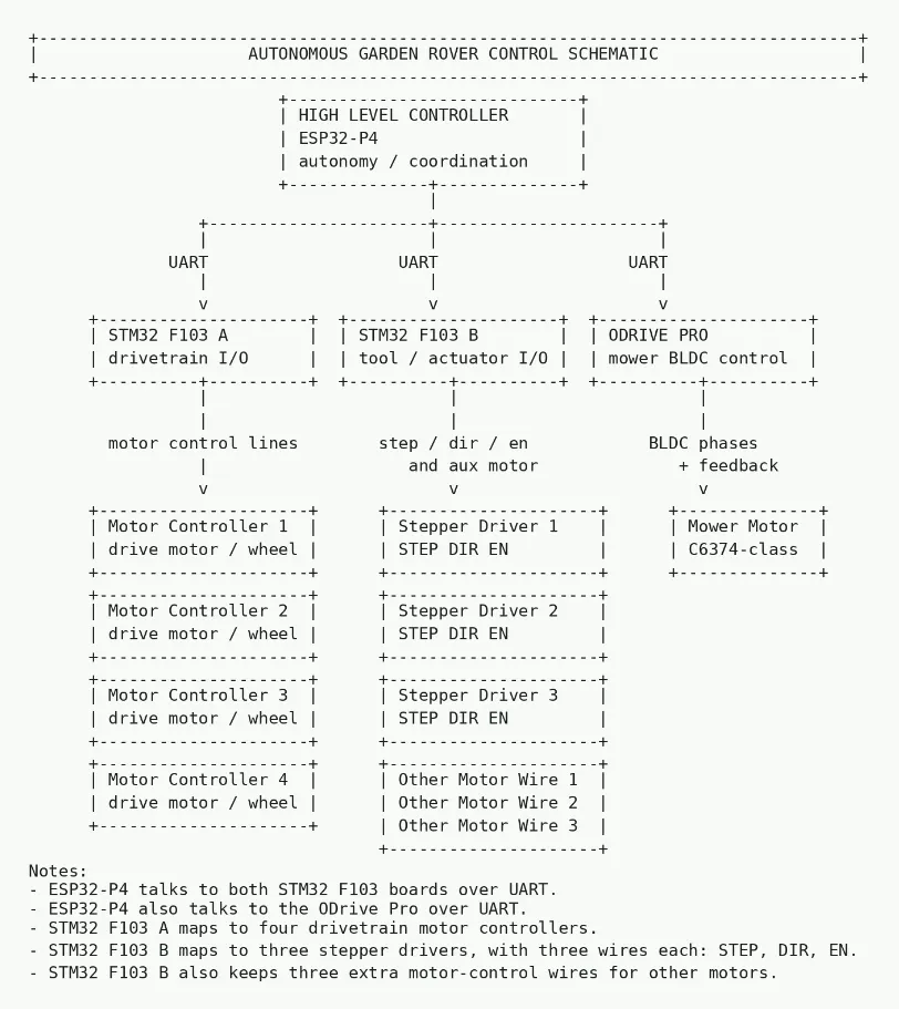
GMS uses a distributed microcontroller architecture:
- ESP32-P4: high-level controller for autonomy logic, subsystem coordination, docking behavior, and overall robot behavior.
- 2x STM32 F103 Blue Pill boards: low-level controllers for timing-sensitive tasks such as encoder reading, motor PWM, BTS7960 control, and sensor I/O.
- BNO085 IMU: orientation and motion sensing.
- Low-cost ODrive-style FOC controller: BLDC mower motor control.
- 36V battery system: main robot power bus, with lower-voltage regulation for logic electronics.
The control split is designed so the ESP32-P4 can make high-level decisions while the STM32 boards handle real-time motor and sensor work.
## Mechanical DesignThe chassis is built from around 16 feet of aluminum channel from Lowe's. I chose aluminum channel because it is inexpensive, easy to cut and modify, and strong enough for an early outdoor robot frame.
The robot is split into two main physical areas:
- Front section: drivetrain, mower module, mower lift, battery placement, and mower electronics.
- Rear section: hose turret, base-station hose interface, and future modular garden tooling.
The front section is mostly complete. The rear section is currently being developed around the hose turret and docking system.
## CAD OrganizationThe CAD folder is organized by subsystem so each part of the robot can be developed separately:
- Turret system: rotating hose turret and worm-drive base.
- Mower subsystem: mower mechanism, blade mounting, protection, lift parts, and frame interfaces.
- Drivetrain: wheel, motor, axle, gearbox, and drive mounting parts.
- Outer frame: chassis pieces, brackets, mounting rails, and exterior support parts.
- Electronics holder: trays and mounts for electronics, wiring, sensors, and power distribution.
- ODrive holder: mount for the mower motor FOC controller.
- Computer holder: mount for the ESP32-P4/high-level control hardware.
- Full robot: top-level assembly combining the complete rover.
The mower module uses a C6374-class BLDC motor on a 36V system. The mower motor is controlled by a low-cost ODrive-style FOC controller. The hardware has high peak capability, but normal cutting should be much lower than the peak rating.
The mower lift uses a custom rope-based mechanism. The goal is to raise and lower the mower without needing a heavy linear actuator or expensive mechanical stage. The mechanism is built, but it still needs repeated load testing, repeatability checks, and safety validation.
## DrivetrainThe drivetrain uses DS3240 servos repurposed as low-cost drive motors. The mechanical drivetrain is built, and the next step is low-level control using the STM32 F103 boards for encoder reading, PWM, motor driver control, and sensor input.
## Hose Turret and WateringThe rear turret is planned as a 2-DOF hose aiming module. Phase 1 is the worm-gear rotating base for the first degree of freedom. The second degree of freedom will raise and lower the hose angle.
The longer-term plan is for the robot to park at a base station, attach or detach a hose, and aim water toward plants. A small pump or container module may also be added later for controlled liquid application. Any liquid testing will start with water.
## RoadmapPhase 1: Mechanical platform
- Build aluminum-channel chassis
- Complete drivetrain mechanical assembly
- Complete front mower module
- Complete rope-based mower lift mechanism
- Mount major front-section hardware
Phase 2: Low-level control
- Wire drivetrain encoders
- Test STM32 F103 encoder reading
- Test BTS7960 motor control
- Send low-level motor and sensor data to the ESP32-P4
- Validate drivetrain movement feedback
Phase 3: Mower control
- Test C6374-class BLDC mower motor control
- Validate ODrive-style FOC controller behavior
- Add safe enable and disable logic
- Add emergency cutoff behavior
- Test mower lift control under load
Phase 4: Rear hose turret
- Complete worm-gear rotating base
- Test first turret degree of freedom
- Build second hose elevation axis
- Add hose mount
- Add base-station hose interface
Phase 5: Base station and watering
- Build hose docking station
- Add controlled water flow
- Add docking alignment sensors or guides
- Test autonomous hose attach/detach behavior
- Test hose pointing repeatability
Phase 6: Autonomous operation
- Add navigation sensors as needed
- Add basic path following
- Add obstacle detection and stop behavior
- Add docking behavior
- Add plant-targeted watering behavior
Phase 7: Field testing
- Test on flat ground
- Test on grass
- Test slope handling
- Test mower height repeatability
- Test watering turret aiming
- Measure runtime, reliability, and thermal behavior
This project includes a 36V electrical system, high-current motor controllers, drive motors, rotating mower hardware, and liquid handling. I treat every subsystem as experimental until it has been tested safely.
My safety plan includes:
- Testing drivetrain behavior with the mower disabled first.
- Keeping people and pets away during powered tests.
- Using fuses, a main disconnect, and emergency shutoff behavior.
- Keeping high-current wiring separated from logic wiring where practical.
- Testing liquid systems with water first.
- Logging failures and updating the design before increasing speed or power.
The next major work is to finish the rear section, continue wiring cleanup, bring up the ESP32-P4 and two STM32 F103 control layers, and test the drivetrain feedback loop. After that, I want to validate the mower lift under load, test the first hose turret axis, and keep documenting the CAD and BOM as the design changes.

_t9PF3orMPd.png?auto=compress%2Cformat&w=40&h=40&fit=fillmax&bg=fff&dpr=2)


Comments