
Hardware components | ||||||
| × | 1 | ||||
| × | 1 | ||||
| × | 1 | ||||
Software apps and online services | ||||||
| ||||||
| ||||||
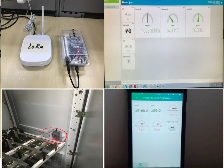
The main objective of this work is to provide an IoT based solution for electrical equipment (i.e. switchgear) that will track its performance and reliability based on its temperature and humidity profile. Common switchgear failure are always associated with an increased heat signature due to wear and tear over time not to mention the loosening contact of busbar joints. Other than common protection device employed, such failures can also be avoided by monitoring temperature and humidity continuously at these critical locations in the switchgear assembly to gain insight into trends or anomalies over time.
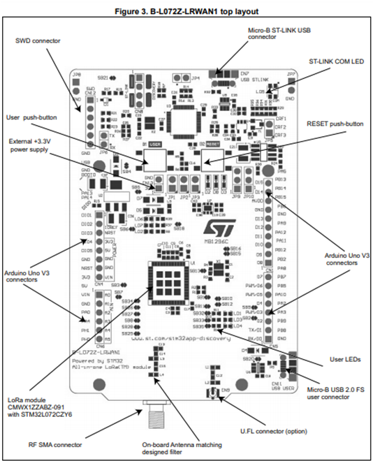
1. LoRa Microcontroller Board (B-l072Z-LRWAN1)
2. Sensor Expansion Board (X-Nucleo-1KS01A2)
3. Ufispace Picocell LoRa Gateway
4. Power Bank
4. Gateway Device Registration to Network Server
The gateway must be register to a network server first before we can use it to relay our sensor data. We will be using Actility Thingpark as our network server. In order to register the gateway to the Thingpark network server, an account must be created from the url https://partners.thingpark.com/. After registering, the following instruction must be executed to add the gateway to the server.
Step 1: Go to the Dashboard
Step 2: Click on the Network Manager as shown in the figure.
Step 3: In the Gateway Management Interface, there is a Create button to click for adding a gateway device.
Step 4: A popup window will appear as shown in the figure.
Select the LRR ID in the Identification mode field. After selecting, you have to fill in few information from the gateway device.
LRR ID: Enter the last BS ID 8 hexadecimal digits (see figure below)
Model : Gateway model which in this case is Ufispace Gateway Picocell v1.5
SMN: Serial Number -> Enter 0000-XX-0000-0000 as SMN (type it manually)
Name : Enter a name for your station
From our gateway, the information will be as shown in the following figure.
Step 5: Click Create and you should be able to see your gateway registered to the Thingpark. Refresh the page to be able to get the latest status.
Following software and driver must me installed before we proceed to coding and testing of the microcontroller.
1. Keil MDK-ARM version 5for STM32L0 url: http://www2.keil.com/mdk5
Note: Once the installation is complete use the below procedure to get a license.
Step 1: Right-click the μVision icon and select Run as Administrator from the context menu.
Step 2: Open the dialog File — License Managementand select the Single-User Licensetab.
Step 3: Click the button Get LIC via Internet, then click the button OK to register the product. This action opens the License Management page on the Keil web site.
Step 4: Enter the Product Serial Number 4PPFW-QBEHZ-M0D5M along with your contact information and click the button Submit. An email is sent back with the License ID Code (LIC)within a few minutes.
Step 5: To activate the Software Product, enter the LIC in the field New License ID Code (LIC) of the dialog License Management and click Add LIC.
2. STMicroelectronics support packageurl:www.keil.com/dd2/Pack/
3. ST-Link USB Driver url: www.st.com/stlinkv2
4. STM32 ST-Link Utility url:www.st.com/stlinkv2
5. Terminal Emulator Software(Teraterm) url:https://ttssh2.osdn.jp/
6. LoRaWAN Firmware Package (I-CUBE-LRWAN) url:www.st.com/i-cube-lrwan
6. Sensor Node/Device Setup and CodingWith all the drivers and software installed, we can load the necessary codes by following the below procedure.
Step 1: Plug-in the Sensor Expansion Board (X-Nucleo-1KS01A2) to the LoRa Microcontroller Board (STM32L072CZY6TR).
Step 2: Connect the antenna as shown in the figure
Step 3: Connect the board to a PC with a USB cable type A to mini-B through USB connector CN1 to the power the board. Then green LED LD3 (PWR) and LD1 (COM) light up.
Step 4: On the window's device manager, check the assign the Com Port number.
Step 5: Open the downloaded package (I-CUBE-LRWAN) earlier and double click the application file as shown below.
Step 6: Click the project option icon and locate the preprocessor symbol settings. Desired frequency must set be set which in our case is REGION_AS923.
Step 7: Right click the Drivers/BSP/X_NUCLEO_IKS01A1 and select Options. Uncheck the Include in Target Build from the popup window as shown.
Step 8: Edit the commissioning.h file and set the value of line 85 to 0.
Step 9: Edit the hw_conf.h file and uncomment the parameter as shown in the figure.
Step 10: Edit the main.c file and uncomment the following line as shown in the figure.
Step 11: Rebuild all files and load the code to the microcontroller.
Step 12: Once completed, open the Tera Term terminal following the settings asshown and click Ok.
Step 13: On the microcontroller, press the black button once to appear the following information from the Tera Term. Take note of this information as it will be used in device registration to network server.
This procedure will show how to register our coded device to the network server.
Step 1: Return to the dashboard interface and click the Device Manager button to enter the device management interface.
Step 2: After entering the Device Management Interface, click the Create button to add the device.
Step 3: Fill in the information as shown in the following figure. The DevEUI, AppEUI, NwkSKey and AppSKey are recorded previously using Tera Term. Please take note that the application routing profile has not been created yet so we have to leave this for a moment.
Step 4: After keying in the information, click the create button. The device is successfully created if you see the device on the list similar to the following figure. You may need to refresh the device list to see the recent status.
Step 5: On the Device Management Interface, click the AS Routing Profile then click create. Fill in the window with the following information and then click Create.
Step 6: On the same interface, click the Application Server and click Create. Fill in the name and Type as shown in the figure.
Step 7: Complete the information as shown in the figure. Take note of adding the destination server address: https://LoRa.mydevices.com/v1/networks/actility/uplink
Step 8: Go back to AS Routing Profiles and add the recently created Application Server.
Step 9: Edit the added Device again and add the routing profile
This section will cover the dashboard creation and visualization of our sensor readings.
We will be using Cayenne Application Server for our project.
Step 1: Create a free myDevices Cayenne account from the following url: https://mydevices.com/
Step 2: Login and add a new LoRa device.
Step 3: Choose Actility from the list and select the STM32 B-L072Z device.
Step 3: Fill in the parameter using the information recorded previously from the Tera Term and click Add device.
Step 4: Customize the dashboard according to our design. Some fidgets may auto populate the dashboard.
After all the setup, we can power the board using a power bank and house our assembly to a small container. Just be sure there is a small opening on the sensor area of the board to get an accurate reading.
There are still a lot of improvement that we can add in our solution. For example, we can a have a smaller sensor with same features that can directly mount on the switchgear busbar itself for more accurate measurement. We could also have a solution whereby we can automatically feed the data to a machine learning algorithm and predict the impending failure or breakdown of the equipment.


Comments