


Hardware components | ||||||
 |
| × | 3 | |||
| × | 8 | ||||
| × | 1 | ||||
| × | 1 | ||||
Hand tools and fabrication machines | ||||||
 |
| |||||
 |
| |||||
We implemented a controller for an online PC game titled “Color Quest” (see link, firefox or safari required). The object of the game is to move your character through an obstacle course, collecting colored coins and power-ups while avoiding obstacles. The normal game controls include left and right movement (‘a’ and ‘d’ keys), laser shoot (‘j’), shield (‘k’), and slow down (‘l’) as well as the ‘space’ key to start the game. To improve the experience, we designed a new, more interactive controller using the onboard KL25Z accelerometer, a series of flex sensors, and Adafruit NeoPixel rings. Rings are normally white but turn different colors to indicate activated powers - red for laser, blue for slow down, and green for shield.
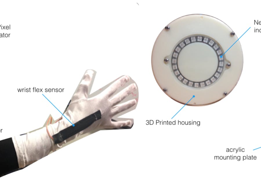
The sensors and LEDs were integrated into two wearable devices - an arm sleeve and chest plate inspired by the Ironman design (see Figure 1 and 2). In the chest plate, we mounted a KL25Z board, a NeoPixel ring, a start button, and a protoboard containing headers for sensor/NeoPixel wires and fixed resistors (see Figure 3 for schematic). The start push button is used to start sending commands from the KL25Z to the game. The housing was made of lasercut acrylic for the board mounting plate and 3D printed ABS for the LED mount. Parts were connected using 4-40 screws. We integrated the flex sensors and another LED strip into an arm sleeve. The LED strip was sewn to the front of the hand while one flex sensor was placed on the back of the wrist and the other on the elbow. When the hand is bent back, as if to say “stop,” the laser powerup is activated. When the elbow is bent with arm across the chest, the shield powerup is activated.
Figure 1: Chest plate with integrated start button, Neopixel ring, KL25Z, and protoboard
Figure 2: Arm Sleeve with Neopixel ring and flex sensors for laser and shield activation
To send commands to the game we utilized the USBKeyboard library to map body movements to the corresponding keys on the keyboard to control the game. To implement moving left and right we used the onboard accelerometer on the KL25z to get the accelerometer readings in the x direction. We then found a threshold value for when the player is turning left or right by printing out the values of the accelerometer and noticed that when the player is upright the x value is around 0 and when the player turns left the x reading goes to -0.5 and when the player turns right the x reading goes to 0.5. We then set the LEAN_LEFT_THRESH, and LEAN_RIGHT_THRESH values to -0.4 and 0.4 respectively. Thus whenever the accelerometer x value was beyond either of the thresholds we sent the corresponding turn left or right key. We implemented the “slow down” button of the game in similar way, by mapping the “slow down” button to when the user leans back in the z direction. We found the LEAN_BACK_THRESH in the same way as the other thresholds. We also mapped the “enter” and “space” keys to the user jumping, which corresponds to a movement in the y direction of the accelerometer. THese were important to include because it is how the game begins. Therefore to start the game you have to jump.
We also created a voltage divider circuit with flex sensors as the variable resistor and a fixed resistor to ground. We then connected an analog input pin to the connection between the flex sensor and the fixed resistor. We picked the fixed resistor according to the equation
R_fixed= SQRT(R_min*R_max)
We measured our flex sensor’s resistance when it was straight(R_min) and bent(R_max) to be
R_min = 10k
R_max = 15k
R_fixed = 12k.
Since we did not have a 12k resistor we just used a 10k resistor instead.
We used two flex sensors. One on the elbow and one on the wrist and then mapped these sensor readings to A0 and A2, respectively. When the flex sensor was flat the reading was ~0.5, but when the flex sensor was bent the readings dropped to below ~0.4 because the flex resistance increased so there was less voltage drop across the fixed resistor. When the wrist flex sensor reading went below 0.4 we sent the ‘laser’ command to the keyboard and when the elbow flex sensor reading went below 0.4 we sent the ‘shield’ command to the keyboard.
We also attached Adafruit NeoPixel rings to the wrist and chest of our device. We made the LED’s blink whatever color corresponded to the action of the game.
Action
Color
nothing
white
shoot
red
shield
green
slow down
blue
In order to ensure that the blinking of the LEDs did not lag the left and right movements in the game we send 5 left commands and 5 right commands whenever the user leaned left or right. We also had a counter in the while loop and incremented it and then modded it by COUNTER_MOD=100.
counter = (counter + 1)%COUNTER_MOD;
and only changed the LED’s whenever the counter ==0.
Figure 3: Circuit schematic and board design
Reflection
We believe that our game controller was a great success. Working with open-minded, and multidisciplinary skilled teammates was key to our success. Our approach encompassed first deciding on the interaction, brainstorming on the most natural ways of playing the chosen game; prototyping the electronics, writing code for each module independently; integrating all the sensors and actuators together; designing and manufacturing the enclosures for a silky-smooth look; and finally assembling everything together.
The only bad occurrences were failing prints, the MicroUSB connector in the KL25Z breaking off.
Working with a microcontroller with one core is difficult if you have multiple moving parts. We tried to implement different light waveforms depending on the command, but using delays to achieve it blocked the rest of the code from running. This made our game laggy as keys were not being sent continuously. In order to fix this, we tried to implement multithreading in the KL25Z. However, this was a difficult task and given the time frame, we decided to drop the multiple light waveform frequencies. Instead, we used modular counters to reduce the amount of times the pulsing command was called, and sent multiple times the x-axis command to smooth it out.
Video


Comments