


Hardware components | ||||||
 |
| × | 1 | |||
| × | 23 | ||||
| × | 22 | ||||
| × | 1 | ||||
| × | 1 | ||||
| × | 1 | ||||
 |
| × | 1 | |||
| × | 1 | ||||
 |
| × | 1 | |||
| × | 8 | ||||
| × | 8 | ||||
 |
| × | 1 | |||
| × | 1 | ||||
| × | 14 | ||||
| × | 2 | ||||
 |
| × | 7 | |||
 |
| × | 1 | |||
| × | 1 | ||||
Software apps and online services | ||||||
 |
| |||||
| ||||||
| ||||||
Hand tools and fabrication machines | ||||||
| ||||||
 |
| |||||
 |
| |||||
 |
| |||||
| ||||||
Pearson Edexcel Level 3 Extended
Project Qualification (EPQ)
Toby Townsend
Score Counter
I play badminton with family once a week, and we're terrible at keeping track of the score and remembering who's supposed to serve next.
AbstractI will develop a device to aid in score counting and player tracking for badminton games, with the flexibility to expand for other game modes. This all stems from my local badminton group finding it difficult to keep track of the score and who is next to serve. I will mitigate this with the application of a microcontroller.
I’ll investigate which microcontroller is most suited to process the logic and manage power requirements.
As I'm interested in PCB design and custom enclosure design, I will develop a PCB which can interface with a robust frame.
I will investigate ways to effectively display a score, balancing the usability with power consumption. A substantial part of this project will be software based; I will investigate ways to control the microcontroller.
Once the device is built, I will analyse the real-world effectiveness and identify any potential oversights.
IntroductionOverviewI often play badminton with family, and we know that it can be hard to keep track of scores when you’re busy playing a match. Sometimes there’s an umpire on hand to help out with this, but people can always make mistakes or have bias towards a team.
I propose an electronic score counter that can have rules and logic programed into it, ruling out human error or bias. It will be optimized for badminton games, as this is a sport I have some prior knowledge in.
To produce this score counting device, research will be conducted to investigate the best methods to display data and ways that the user’s input will be processed. It will then be used to design and program a functional product.
Project CriteriaThe project criteria outline the key functions and requirements.
- Intuitive and easy to use while playing, clearly showing the scores for each team.
- Aid with server selection, tracking who is next to serve.
- Flexibility for different amounts of players and target scores.
- Lightweight and durable.
- Good battery life (>8 hours ).
- Simple and repeatable assembly process.
It is important to break up a project like this into manageable chunks, there’s 4 distinct areas:
- CAD for FDM manufacturing of the enclosure
- PCB design for the manufacturing of the electronics
- C++ Program design for the logic
- Hardware integration with testing methods to optimize user experience
There are many different aspects to this project and many different tools are required to complete them. The required resources are listed below.
- 3D printers - to produce the enclosure
- CAD/CAM software (Fusion 360 & Prusaslicer) - for enclosure design
- PCB design software (EasyPCB) - Schematic & PCB design
- C++ editor (Arduino IDE) - to program the microcontroller
- Soldering equipment - to assemble the PCB
- SMT components - to populate the PCB
- Callipers - for testing tolerances
- DMM - for testing continuity of traces
I have previously made a rough prototype for the score counter project, and I will be using some of the same techniques and ideas in the new design. Therefore, I have included this ‘V1’ prototype in the timeline.
Timeframe breakdown
Phase 1
· V1 development took approximately 15 days. This involved the whole design and manufacturing process.
· Planning ‘Phase 2’ of the project, (which involved the design, manufacturing and testing of V2) will take 1 month.
· Filling out the project proposal form will take about 40 days but will run concurrently with the phase 2 planning.
Phase 2
· Schematic design will take around 2-3 months.
· PCB design will take 1 month, also running semi-concurrently with the schematic design.
· It will the take up to 2 weeks for the PCB to be manufactured and delivered. (JLCPCB, 2022)
· Housing design and manufacturing will take 4-5 months, due to the expected changes in design. This will run concurrently with the schematic and PCB design.
· Coding will take 2 months.
· Integration and testing will take 1 week.
· Another round on PCB design, production and testing has been scheduled to allow for any potential issues with the PCB design.
Phase 3
· User feedback will take 2 weeks and involves recording the feedback from playing badminton while using the device.
· It will the take a week to compile the issues and propose future improvements.
· 2 weeks have been allocated for the design of the presentation.
· The final report and document collation will take about 1 month.
Research reviewGame information· What is the maximum score for a badminton game?
There is conflicting information on this subject. It was originally 15 x 3 rounds for men, 11 x 3 for women. This changed in 2006 when the rules were officially changed to 21 x 3. There is ongoing discussion about transitioning to a new 11 x 5 format, so this may change. (Scroll Staff, 2018)
While the format is called 21 x 3, the score can exceed this in certain cases. For instance, if both teams have 20 points, and another point is scored, the scoring team wouldn’t win due to the requirement of a two-point difference. This can lead to an overrun, if the two-point gap is never achieved by 29-29, the 30th point is the tiebreaker. (BBC, N/A)
If the counter is to accommodate for the largest allowable score, that would mean that 60 LEDs are required for the score alone, not including the other functions. This is a tricky dilemma; either the counter will be excessively large and partially unused, or it won’t comply with the current rules in certain cases and the usability might be affected.
· How many players are involved?
This is an easier question to answer. There have always been two variations of badminton, singles (1 v 1) and doubles (2 v 2). Therefore, we can confidently say that the maximum number of players for badminton is 4. (BBC, N/A)
· 📷What is the standard serving pattern?
When serving, it is common practice to alternate between players, removing the opportunity for any bias. This is simple during singles, alternating between player A and D. (badmintonbites, 2020)
In doubles however, there are 4 positions to alternate between. One method is to follow this pattern: A, D, B, C. This ensures that one team never serves twice in a row, possibly gaining some advantage.
· What distance does the score need to be visible from?
This is an important factor to consider, as the counter should be visible by all players. The BBC provided this useful diagram that labels the dimensions of a standard court.
‘The dimensions of the court are of 13.4 m (44 ft) long and 6.1m (20 ft) wide.’ (BBC, N/A)
Given this information, it can be concluded that the furthest any one player could be from the counter (assuming that it is also located on the court) would be ≈14.72m (corner to corner).
· How important is intuitiveness?
The usefulness of the counter is directly proportional to the intuitiveness, if the counter is bulky and complicated to use, it won’t be used. Making this aspect of the project arguably the most important. To achieve this, an LDR sensor will be used to automatically adjust the LED brightness, making it easy to see in all lighting conditions. A piezo buzzer will also be used to audibly confirm button presses and game events. The battery voltage will also be measured, in order to warn when it is low.
Display MethodsI have researched alternative methods of displaying the score, to improve battery life and visibility.
📷📷7-Segment Displays
+Large value range
-MAX7219 driver needed (128 outputs or 8 x 16 segment displays) (Analog Devices, 2014)
-Hard to read from far away
+Low power consumption (30mA max, with all segments on) (Maxim Intergrated, 2014)
📷Individual LEDs
-Limited value range
-TLC5955 driver needed (48 outputs) (Texas Instruments, 2014)
+Can easily be interpreted from a distance
+Simplifies assembly as only one display method is used for scores and other functions
+Low power consumption (31.9mA max) (Texas Instruments, 2014)
📷Bar LED
-Limited value range
-TLC5955 driver needed (48 outputs) (Texas Instruments, 2014)
+Can easily be seen from a distance
+Uses less space than individual LEDs
+Low power consumption (31.9mA max) (Texas Instruments, 2014)
Differential Display
📷An alternative to displaying the entire score is to display the difference between teams, therefore expanding the value range infinitely (assuming that the scores don’t differ more than the total amount of LEDs). This method could be added at a later date if required.
Individual LEDs offer good versatility and are effective from a distance. As the design is constantly evolving, this added versatility is vital, therefore it is the most suitable option at this time. The option of software updates means that techniques such as a Differential Displays may be used to expand the usable range.
MicrocontrollerThe microcontrollers are made for rapid prototyping, allowing quick alterations to the program, perfect for this use case. I have looked into a range of products (including the Arduino Mega variant, which was used for V1) and compared the features below.
Requirements:
Outputs
· 42 x Score LEDs
· 4 x Player LEDs
· 1 x Low Battery LED
· 1 (3) x Mode LED (RGB requires 3 PWM lines)
· 1 x Buzzer (PWM)
Inputs
· 4 x Score +/- Buttons
· 1 x Reset Button
· 1 x Mode Select Button
· 1 x Battery Voltage
· 1 x LDR
· 1 x Brightness Button
51 Outputs and 9 Inputs, these include:
+2 Analogue inputs.
+4 PWM outputs.
Microcontroller Options:
Arduino Mega (arduino, n.d.)
70 I/O pins, of which:
+16 are Analogue.
+15 have PWM.
This controller has more than enough I/O, analogue an PWM pins for this project. It is the largest of the microcontrollers in this list, size is an important factor when it comes to portability.
Arduino Uno (arduino, n.d.)
20 I/O pins, of which:
+6 are Analogue.
+6 have PWM.
Arduino Nano Every (Arduino, 2019)
22 I/O pins, of which:
+8 are Analogue.
+5 have PWM.
The Uno and Nano models both offer enough analogue and PWM pins but there aren’t enough digital I/O pins to control all the LEDs from the Arduino itself. Therefore, a schematic redesign is needed to reduce the I/O pin requirements, most likely in the form of an LED driver. Despite this, the Nano model is tiny compared to the Mega, this should improve portability.
Raspberry Pi (Raspberry Pi, n.d.)
26 GPIO pins, of which:
+0 are Analogue.
+1 has PWM.
There are many reasons why the Raspberry Pi isn’t suitable for this project, the most glaring one is that it is missing any analogue pins and only has one for PWM. It also has the same issue as the Arduino Nano and Uno controllers, not having enough I/O pins for direct LED control.
Revised requirements (with the TLC5955 driver):
Outputs
· 4 x Control pins for TLC5955 (1 PWM, 1 CLK, 1 MOSI)
· 1 x Low Battery LED
· 1 (3) x Mode LED (RGB requires 3 PWM lines)
· 1 x Buzzer (PWM)
Inputs
· 4 x Score +/- Buttons
· 1 x Reset Button
· 1 x Mode Select Button
· 1 x Battery Voltage
· 1 x LDR
· 1 x Brightness Button
9 Outputs and 9 Inputs, these include:
+2 Analogue inputs.
+5 PWM outputs.
From this selection and analysis, it is clear that the Arduino Nano is most suitable for this project due to its small size and I/O capabilities.
Power supplyThe Arduino Nano Every can powered in 2 different ways, via the USB micro connector or through the VIN pin. The power tree (see below) shows that both the USB and are viable ways of powering the microcontroller. (Arduino, 2023)
Option 1 – USB
To use the 5v USB connector, a regulator would be required. This is due to the lack of any off-the-shelf batteries or cells with a 5v output. DC-DC regulators always have a voltage drop across them, because of this, the input voltage always needs to be > the output voltage. Therefore, the use of a regulator reduces the overall efficiency of the power system.
Another issue with using the USB as the power source, is that it can’t be easily used for diagnostics or code alterations once assembled. A male USB Micro to PCB adapter would also be needed.
On the other hand, this option would provide another level of protection against overvoltage*, protecting the microcontroller from incorrect battery usage or power spikes. *This protection will vary, depending on what regulator is used.
Option 2 – VIN
According to the Arduino website (Arduino, 2019), the VIN pin has an operational voltage range of 7-21v. The official datasheet (Arduino, 2023), which is found on the same page, doesn’t have any information relating to the VIN pin. Despite this, it is safe to assume that a voltage between 7v and 21v will work, due to the Arduino community widely agreeing with this information. (Arduino Community, 2019)
One benefit of using the VIN pin is that the USB port will be free for diagnostics and code alterations. It will also allow for a direct connection onto the PCB, instead of requiring a male USB Micro to PCB adapter.
It should be noted that this option has the same efficiency issues as option 1, due to the Arduino’s internal DC-DC regulator.
Summary
· USB has similar efficiency issues as VIN.
· VINallows for more flexibility with code alteration and testing.
· VINhas a solid-state connection, and a weak point is less likely than with the USB.
Therefore, VIN is the best way to proceed.
Battery Selection
📷📷When it comes to battery selection, there’s three main options available to us. To estimate the current draw from, we can look at the Arduino datasheet as well as the LED driver’s datasheet. Unfortunately, the Arduino Nano Every (the latest generation of Arduino Nano) has an incomplete datasheet.
From my testing, using a multimeter in series with the power source, the idle current draw is 80mA or 100mA peaks. Keep in mind that it will be idle for most of the time, only processing inputs every now and then. With the LED driver drawing a max of 31.9mA (Texas Instruments, 2014), that’s a total of 131.9mA or a rounded 150mA for simplicity. That gives us a power draw of roughly 0.75W (150mA x 5v).
Requirements:
· Minimum supply voltage of 7v.
· Compact size, to fit inside the case.
· Adequate capacity for 8 hours of play (0.75W x 8h = 6Wh)
Option 1 – Multiple Alkaline Cells (5 x AA or AAA)
Alkaline cells (AA and AAA) have a nominal voltage of 1.5v (sparkfun, N/A), deviating from that when new or heavily discharged. Therefore, a minimum of 5 would be needed to achieve the required 7v. However, when these cells are partially discharged, they could drop below the 7v minimum and cause the counter to shut down early.
Using 5 AA batteries would make the device pretty bulky, as each cell is 51mm long and 14mm in diameter and weighs roughly 20g. So that would add an extra 100g minimum to the counter as well as requiring a large holder for all 5 cells.
While the capacity of alkaline cells varies, the typical rating is 2500mAh per cell. (microbattery, N/A) This gives us 18.75Wh (1.5v x 2500mAh x 5 cells), more than enough capacity.
📷It should be noted that these quick calculations do not consider the efficiency of the internal voltage regulator.
Option 2 – Lithium Ion Cells (2 x 3.7v Cells)
Li Ion cells generally have a higher energy density than alkaline, but their main selling point is the rechargeability. Without the need for battery swaps, it can be a sealed unit, leading to a better user experience.
The nominal voltage is 3.7v and, for a similar sized cell to alkaline AA, the capacity is in the range of 700mAh. Meaning that the power available from two cells is 5.92Wh (3.7v x 800mAh x 2 cells).
As only 2 cells are needed to achieve 7v, this allows for a huge space saving compared to alkaline. Typical Li Ion cells with similar dimensions to alkaline equivalents weigh less too, due to their improved energy density.
📷One downside to Li Ion cells is their volatility, if they are mishandled or incorrectly used, they can quickly start a fire. This is why Lincoln college don’t allow them for use in the EPQ. Therefore, I am unable to consider these as an alternative power source.
Option 3 – 9v Battery
📷📷The 9v battery is a compact pack of 6 alkaline cells (1.5v x 6 = 9v). While this reduces the formfactor drawback discussed in option 1, the tradeoff is a smaller capacity. Typical 9v alkaline batteries only have a capacity in the range of 550mAh, compared to standard AA cells’ 2500mAh capacity. (microbattery, N/A)
If a 9v battery was to be used for this project, it would give us 4.95Wh (9v x 550mA). This is short of the required 6Wh to achieve the 8-hour runtime, only giving us approx. 6.6 hours (4.95Wh / 0.75W). (microbattery, N/A)
From these options, the most suitable option is the 9v battery, as it offers a light and compact formfactor at the required voltage.
Schematic ResearchThe schematic provides an overview of the components and how they are connected to each other, it does not include any information on the physical locations or of the layout. Before a schematic can be produced, we need to know what components are going to be used.
Microcontroller
For starters, we will need the Arduino Nano Every board. On easyEDA (a common PCB designer), there is a premade component for the Nano’s footprint and pin layout, so this should be easy to implement.
LED Driver
The second most important component for this project is the LED driver. There are a few options when it comes to LED drivers, but a popular option is the TLC5955, as mentioned in the Display Methods section, it has 48 outputs and can be controlled via SPI. (Texas Instruments, 2014)
Another option is the TLC5940 24-output driver. If the TLC 5940 was to be used, two would be needed to drive all 42 score LEDs. It makes sense to buy a single chip that can run all the LEDs, as these chips will take up a large chunk of space, which might be needed for other components.
Currently chips are hard to source due to the current chip crisis and, since I have access to the larger TLC5955, it is the one which will be used for this score counter project.
LEDs
We will need 42 LED diodes to display the score (21 Red and 21 Blue), as well as 4 (all different colors) to display who is next to serve. An RGB LED will be used to show what game mode the device is in. Then finally, one red LED will be used to indicate a low battery.
Buzzer
To audibly indicate an input, one piezo buzzer will be used to sound different tunes for different actions.
Buttons
Buttons will be used to input different values, 5 for the score alterations (1 +/- for each team and reset), as well as one for the mode selection and one to control the brightness of the LEDs.
LDR
The LDR (Light-Dependent Resistor) can be used to automatically adjust the LED brightness.
Power Switch
This simple component will complete the circuit for the battery and will power on the Arduino.
Battery Connector
A 9v battery somehow needs to be connected to the PCB, the stripped connector wires could be directly soldered on or… The most robust and flexible way would be to add a JST connector, this allows for easy removal of the battery and reduces the risk of a break in the circuit from drops or vibrations.
Passive components
Finally, to make all these components work, a range of resistors and capacitors will be required. This will be discussed in more detail in the PCB Research section.
PCB ResearchTo design the PCB, some information needs to be gathered, specifically information related to the mechanical specifications and core design rules.
TH or SMT?
There are two common mounting families for components, through hole (TH) and surface mount (SMT). TH components are often larger than their SMT counterparts, this is both a good and bad feature, depending on what your PCB requirements are.
📷Through hole technology has been around since the dawn of mass-produced PCBs and was the predominant way to mount components from the 1950s to the 1980s, when surface mount technology gained popularity. That said, TH technology still has its place in modern day PCB design. (raypcb, N/A)
📷Some of the advantages over SMT include:
· Performs better in mechanical loading, for example, a switch which has forces acted upon it regularly.
· Easy assembly, due to larger pins.
Drawbacks include:
· TH components are often larger than their SMT equivalent, making them space inefficient.
· Vias are required, these cause obstructions throughout all layers of the board and can make routing harder.
📷📷
Surface mount technology is a relatively new technology, compared to TH, it was invented in the 1960s but didn’t become mainstream until the 1990s. As the name suggests, this technology mounts the components on the surface of the PCB instead of inserting the pins through the board. (raypcb, N/A)
Advantages include:
· No vias required, therefore other layers of the PCB are unaffected.
· Space efficient, SMT components are often more compact than TH equivalents due to the smaller pins.
Disadvantages include:
· The smaller pins on SMT components can make the assembly process harder.
· Less robust connections, due to the pins being smaller, they are more affected by mechanical loads.
There’s no definitive answer to this question, both mounting technologies have their place in PCB design, some are more suited to TH and others SMT. However, SMT passive components are commonly used to save space due to the large size difference between these types of components.
📷📷
📷📷
📷📷Microcontroller mechanical specs
It is important to know accurate dimensions of your components, these can often be found in the product’s datasheet.
For the Arduino Nano Every, it is 43.18mm long and 17.78mm wide. There are also 4 mounting holes, these won’t be required as the board will be soldered in place. As seen on the data sheet, it comes with a set of unsoldered headers (2 rows of 15), these will be used to mount the board to the PCB.
(Arduino, 2023)📷
Driver mechanical specs
The TLC5955 DCA package, is a small 56-pin device. As it only measures in at 14.1mm long and 8.3mm wide, it means that the pins will be very close together. This is reflected in the datasheet; each pin is 0.27mm wide and there’s just 0.5mm between each pin, giving a separation of about .2mm.
This component will be difficult to solder by hand, especially without a microscope to assist. It will make for a substantial space saving though.
(Texas Instruments, 2014)
Mechanical considerations
📷To mount the PCB to the frame, mounting holes must be incorporated into the PCB. These holes should be equally spread and support the areas likely to have forces acted upon them, such as the buttons.
📷Thermal considerations
As seen on the TLC5955 datasheet, the area under the chip is marked as a thermal pad, this is due to the heat produced by the operation of the driver. If the device overheats, it can be permanently damaged.
To provide some thermal relief, vias and exposed copper areas will be used to pull heat away from the chip and into the PCB. The datasheet suggests that this pad should be soldered to the PCB for optimal thermal transfer, this might be difficult without a reflow oven.
(Texas Instruments, 2014)
How many layers?
📷When it comes to deciding how many layers are needed for your PCB, it is often driven by cost, more layers mean your PCB will cost more to produce. Therefore, PCB engineers strive to make their circuits as compact and space efficient as long as the design rules allow. The number of layers will be decided during the development stage as it is impractical to set a layer limit at this stage.
Design Rules
PCB design software use design rules to aid with trace and component placement, it will warn you if two traces are close enough together to cause interference or a potential short. Other factors, such as trace width are important to consider too, as too much current through any given trace is not only inefficient, but it also heats up and could cause a circuit failure. (Peterson, 2017)
Trace spacing is a relatively easy factor to calculate, especially in DC circuits where interference isn’t much of a concern. The general consensus is that 0.1mm is acceptable for low voltage traces (less than 15v), however digital control signals should follow the ‘3W’ rule, where the width of the trace multiplied by 3 will give you the recommended spacing. (Peterson, 2020)
To calculate the ideal trace width, we must first know what current is expected to pass through it. This can easily be found; all the I/O ports of the Arduino Nano Every are limited to 20mA (Arduino, 2019) and the TLC5955 driver has a sink current limit of 31.9 mA (Texas Instruments, 2014). Most traces on the board will fall under one of those two categories.
The other traces will be power related, the maximum current for these can be found by looking at the Arduino regulators datasheet. In the datasheet (monolithicpower, 2015), maximum power dissipation is said to be 2.7w, given that we can calculate the current with a 9v input. 2.7w / 9v = 0.3A, or 300mA.
📷With that information, we can look to the IPC PCB standards.
All of the traces will be under 1A, so according to the IPC 0.25mm would be fine. It should be said that these numbers are recommended minimums, in reality it would be best to use larger trace widths.
Just to check that these numbers are within the limitations of PCB manufacturing, another source that works in the industry, said:
📷‘For most manufacturers, the minimum trace width should be 6mil or 0.152mm. That limitation comes from their manufacturing (etching) processes and the target yield. But to have some tolerance, we generally use 10-12 mil or 0.254-0.3 mm traces.’ (Robledo, 2021)
That said, I have settled on 0.35mm for the majority of the traces, as most won’t be used to carry large currents. The power, 5v and GND nets will use 0.4mm. While 1mm will be used for the battery terminal connection due to the mechanical strain on these joints.
Discussion / DevelopmentSchematic DevelopmentV1 Schematic
The research for V1 was done before the main research was done, therefore some information is outdated.
📷
📷The Arduino Mega was the microcontroller of choice for V1, purely due to its large I/O offering. Fusion 360 was used to design the schematic.
V1 didn’t utilize an LED driver as this was simply a pathfinding prototype, to find what worked and what didn’t. This version used 30 LEDs to display the score, 15 red and 15 blue. These were all individually connected to the Arduino, using a common cathode with a 220ohm resistor to limit the current. Player LEDs were added to this schematic at a later date but aren’t shown here.
5 buttons were attached, each with a 220ohm pull-down resistor, to digital pins 2 through 6.
The Arduino was powered using the VIN pin, having the positive battery terminal connected to VIN via a switch and the negative terminal connected to GND. To measure the battery voltage, a potential divider was made with a 1:2 ratio. This was done to protect the Arduino’s analogue pin, as the nominal battery voltage is 9v and the maximum input voltage is Vcc+0.5v (5.5v) (baldengineer, 2011). With the potential divider halving that voltage, the highest input voltage should be no higher than 4.5v.
V1.5 Schematic
This was a design made during the LED driver research stage, to test out the viability of using multiple drivers. easyEDA was used instead of fusion 360 due to the larger component library and improved tools.
The initial design (V1) used the Arduino Mega to control all 30 score LEDs. This worked perfectly well but isn’t efficient by any means, drawing ~600mA for the LEDs alone (30 x 20mA (max I/O output)) (arduino, 2023). Using an LED driver, only one LED is ever on at once, reducing that current draw to just 20mA (120mA max). (Instruments, 2015)
📷📷This schematic uses 3 TLC5940 LED drivers, all connected to each other, to produce 48 outputs (3 x 16 channels). Using the TLC5940 datasheet, the pins were connected to the required ports and various power connections. (Instruments, 2015)
In addition to the LED drivers, a 6th button was added to change game mode. The buzzer was also implemented, using a PWM pin on the Arduino Nano, and grounded via a resistor to limit the current.
The microcontroller also changed for this design, using the Arduino Nano Every instead of the Mega. This was done due to test out the smaller controller, making sure there was enough I/O pins with the necessary features (such as PWM).
V2 Schematic
For V2, there was a clear plan for what circuitry and components were going to be used.
Requirements:
· Arduino Nano Every
· TLC5955 LED driver
· 42 score LEDs
· 4 player LEDs
· Low Battery LED
· RGB mode LED
· Piezo buzzer
· 7 buttons
· LDR
· Power switch
· Battery connector & measurement circuitry
· Various passive components
The TLC5955 driver uses SPI to communicate with the Arduino, therefore only requiring 4 connections:
· GSCLK – Reference clock for the grayscale, pulse width modulation control for all outputs.
· LAT – Used to latch the output.
· SIN – Serial data input (requires the MOSI pin).
‘MOSI—Master Output Slave Input—transmits data from the master to a slave, while MISO—Master Input Slave Output—transmits data from the slave to the master.’ (Arrow, 2019)
· SCLK – Serial data shift clock, used to sync the timing across SPI devices.
(Texas Instruments, 2014)
Arduino connections to TLC5955:
· GSCLK – Pin 3 (as it requires PWM control)
· LAT – Pin 4 (basic digital control, pin 4 was free)
· SIN – Pin 11 (requires the MOSI pin to operate)
· 📷📷📷SCLK – Pin 13 (SPI pin on the Arduino Nano Every)
📷📷📷📷📷This design implements all the above-mentioned features into one schematic. This design was made using easyEDA, a free to use, PCB and schematic design software.
Using the TLC5955 LED driver (48 channel) simplifies the PCB layout and reduces the total footprint of the driver elements.
All the LED cathodes are connected to the driver outputs, then the anodes are all connected to 5v. Then the control pins are connected as previously discussed, and the 5v and GND connections are made in accordance with the pinout diagram found in the datasheet.
(Texas Instruments, 2014)
The RGB Mode LED will indicate the current game mode through different colors, this is achieved by 3 PWM pins. While it is possible for the TLC5955 to control this, there isn’t enough outputs due to 47 of the 48 being used for other LEDs. Therefore, it must be controlled using the Arduino’s PWM pins D5, D9, D10. It’s true that the player LEDs could be moved from the driver instead, but I believe it will be simpler to have this element controlled independently.
Current limiting resistors have been added to the anode of each LED.
📷To read the LDR, a simple potential divider setup is used, using the Analog pin to measure the change in voltage.
R7 in this schematic is the LDR and R12 is the other half of the potential divider. R12 is grounded and R7 is at 5v, the center point is then tapped and sent to analogue pin A0.
Then, once set up in the software, it will be used to reduce power consumption by adjusting the LED brightness to suit the measured ambient light level.
To measure the battery voltage, a 1:2 ratio potential divider is used.
📷(The image to the right has incorrect resistor values, one should be double the resistance of the other).
As mentioned previously, this was done to protect the Arduino’s analogue pin, as the nominal battery voltage is 9v and the maximum input voltage is Vcc+0.5v (5.5v) (baldengineer, 2011). The potential divider halves the voltage, making highest input voltage no higher than 4.5v. The pin used for this analogue measurement is A7.
📷📷Sometimes it is difficult for the players to see when a point has been added / removed. To provide reassurance that the score has been updated correctly, a buzzer component will give a unique audio confirmation tune for each function. To enable / disable this buzzer, I have adapted the power switch, as seen here. The orange lines are connected to D7 and D8 on the Arduino, this will allow for two on-states, one with sound and one without.
📷📷This is possible due to the type of switch used, it is called DPDT, meaning Dual Pole Dual Throw. AKA, it is two switches in one, both with two on positions.
📷To control the buzzer, 1 PWM pin is needed, D6 will be used. The negative terminal of the buzzer will be connected to ground via a resistor to limit the current and therefore the volume. This value can be changed at a later date, depending on how loud it is.
The button input circuitry is relatively simple, pull-down resistors are used to prevent the input from floating. These resistance values are placeholders.
As the button inputs are digital, either 5V or 0V (ideally), any spare I/O pin can be used for this purpose. As they’re available, A1-A6 and D8 will be used.
V2.1 Schematic
V2.1 is a slightly altered version of V2, adding some small improvements.
To start with, one 20v Zener diode (1N4747A) has been added to the VIN connection, this will protect the Arduino from overvoltage damage in the event that the batteries are incorrectly used. (onsemi, 2009)
Another battery connection has been added, to improve flexibility during the case design and build stage.
One buffer capacitor has been added between VIN and GND, this should help smooth out the input voltage in case of a poor-quality battery or loose connection.
There are also two filtering capacitors, one for each battery, to again smooth out the voltage. Looking back at this decision, it was unnecessary as the Arduino has internal capacitors.
After looking back at the TLC5955’s datasheet, one capacitor was omitted from the previous design. (Texas Instruments, 2014) It is connected between 5v and GND.
Finally, duplicate components have been added, one being SMT and one TH. This allows for better flexibility during the build stage and will be expanded upon in the PCB development stage.
PCB DevelopmentThe PCB (Printed Circuit Board) houses all the electronic components and is designed following a schematic. For V1 a PCB wasn’t used as it was a rough pathfinding prototype. This resulted in a rat’s nest of wires and hot glue, and it will inevitably fail at some point due to a poor solder joint or loose connection.
V2 will avoid these issues by making everything solid-state, avoiding the use of jumper wires and instead using traces on the PCB. One bonus that comes with using a PCB is the compactification, having all the components on one board means that less space is needed.
Component placement
The user interface (UI) components (LEDs and buttons) must be well organized to make the device as easy to use as possible. To achieve this, a grouping method has been used, grouping similar functions in the same general area.
For V1, this grouping layout was used:
· Score buttons +/-
· Player LEDs
· Score LEDs
· 📷📷Utility components (reset button, low battery LED, and power switch)
In the V2 design, more features have been added, therefore a new grouping layout was required:
· Score buttons +/- and reset button
· LDR / Brightness control
· Player LEDs
· Game mode LED and button
· Low battery LED
· Power switch
· Red score LEDs
· 📷
Blue score LEDs
To make the device visually appealing and easier to understand, a symmetrical design has been used. This separates the score LEDs into two groups, red and blue. The score buttons have been kept close to the edge as this was found to work well in V1.
Board size
In order to make the score counter as portable as possible, the PCB needs to be as small as possible, while retaining the functionality. The limiting factor for board size are the LEDs, each LED has a diameter of 5mm (5.8 at the base) (MultiComp, 2011). With 21 LEDs and a 5mm gap between each one and 5mm at the end, the length will be 220mm. This can be reduced to 150mm with 2mm gaps and 2.5mm margin on the ends.
The width is determined by the Arduino (the largest single component), it is 43.18mm long. Due to through hole LEDs either side of it, the minimum width increases to ~65mm. Adding a bit of margin around the edges of the board gives a more realistic value of 70mm.
Routing
📷
Before these components can be connected using traces, the design rules need to be set. These were decided during the research phase.
With the design rules in place, auto routing can be used to connect the components. It does this using the connections found in the schematic.
Various non-UI component layouts were experimented with.
Pull-down and current limiting resistors were placed next to their component, and the battery connector was placed near to the power switch.
📷📷Originally the Arduino and LED driver were located near to the center of the board, this was done to shorten the average distance between the controller and the components. Unfortunately, it was proving difficult to route all the connections in such a compact area, especially with TH LEDs and buttons creating obstacles.
To make more room for traces, the Arduino and LED driver were moved apart. This meant that the battery connectors had to move to the other side of the power switch. SMT resistors and capacitors have also been used in favor of TH, this is to reduce footprint taken up by passive components. Mounting holes have been added across the board, an additional 2 are located near the buttons, to reinforce the board.
📷📷
Silkscreen
The silkscreen is mainly used to assist in PCB assembly, showing where components should be positioned. In addition to these component names and outlines, areas have been marked around the mounting holes, these indicate trace-free areas which can be used for mechanical purposes.
The text ‘JLCJLCJLCJLC’ is used by the PCB manufacturer to attach a serial number in a non-intrusive area.
Heatsink
To provide passive cooling to the LED driver, an area of exposed copper has been added onto the top side of the PCB. It is connected to a smaller exposed copper area (under the driver’s heatsink) using vias, the entire heatsink is connected to the ground plane, this should move the heat away from the IC to the board.
Test pads (5v, GND, ALT_SW)
Test pads for +5V and GND nets have been added. as well as a wider area to mount a different switch as well as an ‘ALT_SW’ point which can be used to add a side-mounted or external switch.
📷📷
Pre-manufacturing checks
While I hope everything works perfectly first time, there is a good chance it won’t. That’s why additional time has been baked into the Gantt chart for a PCB revision, this ensures that any issues don’t cause a major delay to the overall timeline.
Before the PCB is sent off for manufacturing, some changes have been made to make it as flexible as possible. Options have been built in to allow minor design changes without the need for a new board.
· The Zener diode (D1) has been made compatible for both TH and SMT mounting.
· There are also two battery connectors, this will allow for an alternative power source to be added in future (either a secondary battery or an external source).
· The option to bypass the PWR_SW, allows the use of an external switch (ALT_SW)
There’s a limit on how much flexibility can be added before the design as a whole is negatively impacted. For example, this design will only work with the Arduino Nano Every microcontroller. So, if a different microcontroller needs to be used, a new board design will be required. To a further extent, the PCB is firmly locked to the TLC5955, due to its unique pinout.
Finally, a DRC (design rule check) was run in EasyEDA, this confirms that all traces adhere to the design rules. The Gerber files can now be exported and sent to the manufacturer.
Manufacturing
The PCB is now ready for manufacturing, JLC PCB will be used as it has a quick turnaround, taking roughly 24 hours to manufacture and 5-8 business days to be delivered. (JLCPCB, 2022)
📷📷
📷📷
Code DevelopmentV1 code: (Townsend, 2022)
Requirements:
· The score LEDs will increase by one every time the corresponding + button is pressed.
· The score LEDs will decrease by one every time the corresponding - button is pressed.
· The reset button will cause the score to reset and all score LEDs to be turned off, and a random player will be selected.
· The current player’s LED will light up.
· The current player will increase by one every time a + button is used and decrease every time a – button is used.
Setup
The setup function is used to set ‘pinModes’ and the starting score, among others.
📷📷
Variables
📷📷The variables are used to label static input / output pins as well as dynamic values, including score and player info.
📷
Functions
Functions are blocks of code that can be called upon to perform regularly used tasks.
‘inputCheck()’ – Checks the inputs and performs the related action, after some logic checks. Game logic is also found in this function, checking for a win condition.
(e.g., if the ‘BLUE_ADD’ input is HIGH and the current ‘blueScore’ is less than the ‘maxScore’, then add one to ‘blueScore’.)
(e.g., if the ‘blueScore’ equals the ‘maxScore’ then trigger a blue team win condition by calling the ‘gameEnd(2)’ function.)
‘playerSelect(i)’ – Performs player related actions.
(e.g., ‘playerSelect(0)’ adds one to the ‘player’ variable if ‘player’ is less than 4, if it is greater than 4 it rolls around to player 1.)
‘outputCheck()’ – Updates the outputs
(e.g., if ‘blueScore’ equals 9, set ‘BLUE_PINS[0-8]’ HIGH.)
‘gameEnd(i)’ – Used to perform end of game and game reset actions.
(e.g., ‘gameEnd(1)’ turns the ‘RED_PINS[0-14]’ on (runs ‘outputCheck) and then off (runs ‘outputCheck) with a delay defined by ‘winDelay’ and repeats a number of times defined by the ‘winFlash’ variable. It then sets ‘blueScore’ and ‘redScore’ to 0, and runs the ‘outputCheck’ function to update the LEDs)
‘status()’ – Used to output a status update via the serial connection.
(e.g., The current ‘redScore’ is printed to the serial connection.)
‘powerCheck() – Measures the analogue input of the battery.
(Analogue input ‘BATT’ is read and said value is processed and written to ‘BATT_V’ variable. ‘BATT_V’ is then processed again to give a battery charge percentage ‘BATT_Level’, if it is less than 50%, the ‘LOW_BATT’ output is set HIGH.)
‘setup()’ – Ran once at the start of the program, houses setup code.
‘loop()’ – Continually runs in a loop until the program stops, houses a high-level order of operations.
(‘inputCheck’, ‘outputCheck’, ‘status’)
Summary
To summarize, the inputs are continually read, logic is applied to create a score and player value, these values are then sent to various outputs.
V2 Code: (Townsend, 2023)
Overview
Learning from code used in V1, some new features have been implemented alongside the introduction of the TLC5955 LED driver.
Requirements:
· The score LEDs will increase by one every time the corresponding + button is pressed.
· The score LEDs will decrease by one every time the corresponding - button is pressed.
· The reset button will cause the score to reset and all score LEDs to be turned off, and a random player will be selected.
· The current player’s LED will light up.
· The current player will increase by one every time a + button is used and decrease every time a – button is used, following the pattern described in the research stage.
· Different game modes will be selected using the game mode button. Different game modes will have different max scores and player counts (21x4, 21x2, 15x4, 15x2, 10x4, 10x2, 5x4, 5x2).
· The low battery LED will turn on when the battery is predicted to be below 20%.
· Different brightness settings are selected using the brightness (LDR_EN) button (LOW, MEDIUM, HIGH, AUTO).
· The buzzer will make unique sounds for different button presses and game events.
· The buzzer can be disabled using the power switch.
Libraries and setup
As the LEDs are now being controlled by the LED driver instead of the direct I/O connection used in V1, a library is required to interface with it. This particular LED driver has many features that won’t be needed, all I need to do is set individual LEDs to HIGH or LOW and for them to stay on. There are control bits which control the way the driver behaves (such as max channel current) and there are bits that control the state of the outputs. I need to find those addresses so that the code can change specific bits when an LED should change state.
My original plan was to write to these bits manually by effectively writing my own library, this would have taken a lot longer and probably wouldn’t work as intended. Instead of making my own library, I looked for compatible ones online.
Test code made for the TLC5955 was found on this site (StudentSA, 2015). Unfortunately, it only compiles for the original Arduino nano and Arduino mega but not the newer Nano Every. This is because of the new processer having different registers (ATmega4809) (Doc_Arduino, 2021).
One library made for the TLC5951 looks like the best option (Lorthioir, 2014). While the TLC5951 has only 24-Channels compared to the TLC5955’s 48, this shouldn’t be too hard to change as they both have similar internal architecture. (Texas Instruments, 2014) (Texas Instruments, 2017)
📷📷After working on the TLC5951 to TLC5955 library conversion, it was uploaded to the board. The LEDs flashed randomly, suggesting that the wrong bits are being written to. Some minor tweaks to the configuration fixed this.
📷📷Variables
📷📷The variables are used to label static input / output pin locations as well as dynamic values, including score and player info.
📷📷Functions
Functions are blocks of code that can be called upon to perform regularly used tasks.📷📷
‘LED_Update(Group, Number, Value)’ – Simplifies the interface with the LED driver.
(e.g., ‘LED_Update(1,6,255)’ will set the output for LED 6 in group 1 to a value of 255. This is done using the ‘LED_LOCATION’ matrix.)
‘mode_LED_Update()’ – Updates the mode LED to the correct values.
(It will check the current ‘mode’ and write values found in the ‘Mode_RGB’ matrix to LED outputs ‘Mode_LED’, only after being adjusted by the current ‘brightness’ setting.)
‘displayUpdate(displayMode)’ - Updates the outputs for score and player LEDs, also has the ability to hold the active player LEDs on during a game mode change.
(e.g., If ‘redScore’ is 16, ‘LED_Update’ function is used to set red LEDs 0 to 15 HIGH.)
(e.g., If ‘displayMode’ equals 1 (hold mode), all active player LEDs are set HIGH using the ‘LED_Update’ function, until ‘displayMode equals 0, where the current ‘player’ LED is set HIGH and the rest are set LOW.)
‘buzzer(ID)’ – Used to interface with the ‘BUZZER’ output.
(If ‘sound’ is TRUE, the ‘BUZZER’ output is sent signals. These are made using the information from the ‘melody’ matrix and ‘ID’ integer, when fed into the built-in ‘tone(tune, duration)’ function.)
‘inputCheck’ - Checks the inputs and performs the related action, after some logic checks. Game logic is also found in this function, checking for a win condition. The buzzer function is also called.
(e.g., if the ‘BLUE_ADD’ input is HIGH and the current ‘blueScore’ is less than the ‘maxScore’, then add one to ‘blueScore’.)
(e.g., if the ‘blueScore’ equals the ‘maxScore’ then trigger a blue team win condition by calling the ‘gameEnd(2)’ function.)
(A ‘delay_cycle’ is also used, only allowing the previous actions to happen if the delay cycle is equal to ‘inputDelay’, this prevents one click from being interpreted as multiple.
‘playerSelect(operation)’ - Performs player related actions.
(e.g., If ‘operation’ equals 2 (random selection), a ‘tempPlayer’ is made to log the current player, then ‘player is randomly selected. If ‘player’ is the same as ‘tempPlayer’ then ‘operation’ 2 is called again, this was done to ensure that the same player isn’t selected again as the user might think that the input wasn’t recognized.)
‘gameEnd(endMode)’ – Used to perform end of game and game reset actions. The ‘playerSelect’ function is also called to randomize the ‘player’.
(e.g., ‘gameEnd(1)’ calls ‘displayUpdate’ to turn on and then off all red LEDs (while also calling the ‘buzzer’ function), using defined delay ‘winDelay’ and repeats a number of times defined by the ‘winFlash’ variable. It then sets ‘blueScore’ and ‘redScore’ to 0, and runs the ‘displayUpdate’ function to update the LEDs)
‘status(period)’ – Used to output a status update via the serial connection every specified amount of time.
(e.g., The current ‘redScore’ is printed to the serial connection if ‘cycleCount’ equals ‘period’)
‘powerCheck() – Measures the analogue input of the battery.
(Analogue input ‘BATT’ is read and said value is processed and written to ‘battVoltage’ variable. ‘battVoltage’ is then processed again to give a battery charge percentage ‘battLevel’, if it is less than 20%, ‘lowBatt’ is set to TRUE)
‘dynBrightness()’ – Controls the brightness modes, including the automatic brightness feature.
(The ‘brightnessMode’ is set by the ‘inputCheck’ function, there are 4 modes: LOW, MEDIUM, HIGH, AUTO. ‘brightness’ integer is set to preset values for the first three modes, but for the AUTO mode, brightness is set to the analogue voltage reading ‘LDR’ after some intermediary processing.
(A temporary brightness integer ‘temp’ is made at the start of the function, it is then compared with the current ‘brightness’ value, if they don’t match then a piece of code is run to update the LED driver’s brightness setting. This prevents excessive flashing from the settings being continually updated.)
‘gameMode(playerDisplayHold)’ – Controls game mode rules and calls ‘displayUpdate’ to show current game settings.
(Sets the current ‘playerCount’ and ‘maxScore’ according to the ‘GMrules’ matrix. It also passes along ‘playerDisplayHold’ along to ‘displayUpdate’, to enable game-mode-change display hold, this allows users to temporarily view the selected game mode settings)
‘blink()’ – This function is called every time the LEDs should be updated, it calls all the functions that will update the LEDs so that they are all done at the same time. By coordinating the LED’s ‘blink’, less blinking is taking place, leading to a more stable-looking display.
‘setup()’ – Ran once at the start of the program, houses setup code.
(Includes LED driver setup and checks if ‘sound’ is enabled by reading ‘SOUND_EN’.)
‘loop()’ – Continually runs in a loop until the program stops, houses a high-level order of operations.
(‘inputCheck’, ‘powerCheck’)
Summary
To summarize, inputs are continually read, logic applied, and multiple outputs are sent. The LED driver requires slightly more processing, but outputs are sent, nonetheless.
What was improved?
The LEDs now run more efficiently with the use of the LED driver. More features have been added, including different game modes and the addition of an audio element.
What needs improving?
· More distinct sounds would help identify different game events / user inputs.
· Implementation of the RGB mode LED.
· Improved functionality of the low battery LED, allowing it to work with rechargeable batteries (if possible).
·
Case DevelopmentV1 Case
The case design for V1 was pretty simple, consisting of two main parts:
The body had 6 mounting points for the Arduino Mega (arduino, 2023), which was secured using M2.5 x 10mm bolts, and one access hole for the data port. The access panel for the battery is a small removeable cutout, secured by two M3 x 10mm bolts, a small bracket was also added to hold the battery in place.
📷📷📷📷The front panel had holes for the LEDs, buttons, and power switch, with some basic grouping lines. On the back it had routes carved out for the wiring, space was also made for the button support bracket. Two M3 bolts were used to secure the front panel, thread through the sides of the body into embedded nuts inside the front panel.
Once the design had been finalized, the parts were 3D printed. To achieve the white lining found on the front panel, the filament was changed to white for two layers, then changed back to black. Embedded nuts in the main body (for the Arduino mounting points) were placed when a scheduled pause layer was reached. Embedding components in this way makes for an easier build process, as the nuts won’t fall out when the Arduino is removed.
V2 Design
Using the knowledge gained from the design process of V1, V2 could use parts that work and improve parts that didn’t work as well.
PCB Attachment
📷📷The PCB will be directly attached to the front panel, this simplifies the build process as circuit testing can be done while the case is installed. The 8 mounting points are arranged to match up to the PCB’s holes, 6 of the 8 M2.5 bolts are used to secure the PCB as well as the rear panel, this reduces the total number of required bolts and strenthens the entire assembly.
Port Access
As seen on the image above, there is an alternative power port (marked with ‘PWR’). This is the unused battery connector and might be used for manual battery voltage readings or to power the device externally.
📷📷To access the onboard data port on the Arduino, a small hole has been made in the case. It is marked with a USB logo indentation.
📷📷A later addition to V2, made during the build process, was the use of a rechargable 9V battery. This rechargable battery has a micro USB port for recharging, therefore requires another access port. It has been marked with a battery icon.
UI Groups
The user interface groups, discussed in the research and PCB development stage, have been implemented and outlined on the front panel. Using the same method as V1, changing to white for two layers and then back to black again.
Form Factor
The overall design is much thinner than V1 and could be thinner if it wasn’t limited by the battery. There are two options:
📷📷Variation A uses a larger back panel to house the battery with a separate battery mount.
The back panel makes this variation more suited to stationary usage, such as on a table or bench as it has multiple stable viewing positions 0°, 45° and 90°.
Variation B removes the larger back panel and instead houses the battery directly in an extended body, not requiring a separate mount. This extended body also doubles as a grip / handle.
The flat back panel on variation B is only stable in two positions 0° and 90°. Making it better suited as a portable device with its lighter, thinner form factor. Having a dedicated grip should also assist with fast operation during a game.
As the original project requirements ask for a lightweight device, variation B is currently the best option of the two.
Buttons
📷The buttons are too short to reach when the case is fitted. This is due to the PWR_SW being quite tall, protruding 8.2mm (from PCB to the outer edge of the case). Compared to the 4mm protrusion of the button.
There are a couple options to fix this, I can either use taller buttons (which are available with the same footprint), or I could design a printable button insert that would sit between the button and the case (acting as an extender).
After reviewing the pros and cons, the ‘Button Extender’ option appears to be the quickest and most cost-effective option.
V1 BuildThe V1 design was done before the research stage, therefore some information is outdated but has been included to provide context.
Prep
These tools and materials were used for the V1 build process:
- Soldering iron
- Brass solder-remover
- Lead-free solder
- Solder wick
- Flux
- Tweezers
- Fume extractor
- Component organiser
- Hot glue gun
Front panel assembly
The first print had tolerance issues; the LEDs didn’t quite fit (due to misalignment). Those tolerances were adjusted, and it was reprinted.
Once the reprinted panel was ready, the LEDs were loosely installed. While the resistors and buttons sat well, the LEDs were a bit loose. To prevent them from becoming dislodged, hot glue was used to secure them after wires were soldered on to each leg of the LED.
📷📷📷
Figure 65 - Components installed in the front panel.
Figure 65 - Components installed in the front panel.
📷📷
Small jumper wires were used to connect the button and power switch circuitry. Once the electronics were installed, the button reinforcer was bolted in place.
Arduino installation
The Arduino Mega was placed inside the case and secured with 6 M2.5 bolts. Once secured, the connectors could be connected to the Arduino, this was done using tweezers. Labels on the wires helped to identify which connector goes where.
The front panel can now be attached using 2 M3 bolts, closing out the case.
📷📷📷
Battery installation
With the wires all connected, the battery holder could be installed and so could the battery itself. Finally, the battery panel could be attached wih 2 M3 bolts.
Summary
This design wasn’t easy to assemble and is prone to breakages due to the large number of unsecured connections and free-floating solder joints. The use of hot glue also made it hard to fault-find as all the connections were inaccessible without removing the glue, a better solution would be a tighter fitting front panel.
Future designs should use less wires and avoid the use of hot glue.
V2 BuildOnce all the components have been made and delivered, the assembly process could begin.
Prep
To prepare the workshop for PCB assembly, some tools were needed:
- Soldering iron
- Brass solder-remover
- Lead-free solder
- Solder wick
- Flux
- IPA (Isopropyl alcohol)
- Cotton buds
- Cocktail sticks
- PCB / tool hex holder
- Tweezers
- Fume extractor
- Component organiser
📷📷
Figure 69 – Brass solder-remover
Figure 69 – Brass solder-remover
Figure 70 - Flux
Figure 70 - Flux
📷📷
📷
Before the build can start a bill of materials should be made, this lists the quantity of all the required components, both electrical and mechanical. (Townsend, 2023)
PCB assembly
The components were organised, the PCB was in the holder, fume extractor was on, and the soldering iron was heated, time to start fluxing the board.
The first step to assembling the PCB is preparing the area you are working on, while it varies between components, it’s common practice to apply flux. This can be done using a cocktail stick and helps to stick the component in the right place.
I started with the smallest components and worked up from there. The resistors and capacitors used are SMT 0603 packages, smaller than the tip of a pen. They come on a strip, as they’re normally used in pick and place machines. I sourced a SMT resistor & capacitor sample book for this project as they contain a large range of values and will allow for value alterations if needed.
Figure 76 - Strip of 0603 Resistors
Figure 76 - Strip of 0603 Resistors
Placing the correct components according to the schematic is easy, as the silkscreen labels show where they should be placed. The flux acts like glue once the components are set down, so the tweezers came in handy to adjust the position. I then applied heat and solder to secure it in place. This was repeated for all the resistors and C4.
C1, C2, C3 will not be fitted at this time. They were only intended as an optional component, to be added if there are stability issues with the power supply. D1 is bridged with a 0Ω resistor for the time being, the intended 20v Zener will be fitted later (if required).
📷The hardest component to fit was the LED driver. The DCAR package has 56 pins (28 on each side) all with less than 0.5mm between pins.
Positioning the chip was quite difficult, flux helped to hold it in place while I adjusted the positioning with tweezers until the pins aligned with the pads. I then soldered down two opposite pins to secure it, after a while of adjusting I was happy to continue to attach the other pins. I noticed that the pins were bridging when the solder was applied, this will be due to the large iron tip, ideally a smaller set of rework tweezers would be used.
📷After some trial and error (and a lot of flux), I managed to get all the pins down, removing excess solder with the solder wick.
This document by Infineon helped. Titled ‘Recommendations for Printed Circuit Board Assembly of Infineon PG-TSSOP-38-4 Packages’ (infineon, 2006).
I then moved on to fit the buttons, placing them all on the board then applying flux and solder.
After that, all the LEDs were placed in the correct positions (ensuring correct polarity), flux was then applied to all the legs. Once that was done, the legs could be soldered in place and the excess removed, continually checking that they are flat against the PCB.
📷📷📷📷📷Continued to fit the buzzer, LDR, BATT1 & BATT2 connectors, following the same procedures as described previously. The power switch is friction fitted once integrated with the case.
Finally, the Arduino could be installed. Soldering the two end pins to the Arduino, ensuring that they are flush with the board before soldering the rest. After soldering the Arduino to pin connections, I did the same for the pin to PCB connections.
Once everything was installed, I went over the board with an IPA-soaked cotton bud, removing the flux residue.
This section of the project took a lot longer than anticipated, taking 2-3 weeks instead of the originally planned 1 week.
Case integration
A fit test with the front panel was done, it had a few issues:
- Some of the Arduino pins don’t have enough clearance.
(Due to a modelling inaccuracy)
- The back panel is too weak around the battery bay, resulting in it bending outwards.
(This is easily fixable; the back panel will be thickened by 1mm and 1mm will be taken from the front panel)
- The battery charging port is misaligned.
(Due to a modelling inaccuracy)
- The data port is misaligned.
(Due to a modelling inaccuracy)
- Button extenders are too tight.
(The button extenders are designed to fit with very little space between them and the case, this was done to stop them from rattling. This resulted in them fitting too tightly, making them remain pressed after released. The distance will be increased by 0.05mm to resolve this issue)
- Some LEDs aren’t aligned.
(Due to the LEDs being soldered by hand there is a margin of error which wasn’t fully accounted for, I could go through and reposition each LED until it fits but since a reprint is already needed, I might as well adjust the tolerances)
- The internal battery connector wires don’t fit.
(The battery connector is almost flush with the back panel; this doesn’t leave enough space for the wires coming from the connector to bend)
- Noticeable warping
(The large size means that it is prone to warping, in addition to being on a textured bed and brimless, it resulted in a noticeable warp. While not affecting the overall use of the device, it could result in a print failure. I’ll remove the chamfer and add a small brim)
The changes have been implemented and the case reprinted. All 7 button extenders were installed then the PCB was placed on top and secured with 2 M2.5 screws.
📷The new case still has a couple minor issues which could be easily fixed in the future:
- The back panel locking edge isn’t flush.
(This edge was introduced to stop the battery bay cover from lifting. Now that it doesn’t sit flush with the case, the tolerances must need adjusting)
- The USB data port isn’t positioned as intended.
(The model showed the Arduino to be closer to the edge than it is, this is a minor issue that can be resolved easily)
- Battery connector removed.
(To maintain the slim formfactor, I simply removed the internal battery connector and directly soldered the wires to the board. While this should be fine as the battery can still be removed, it does introduce a potential weak point, which could result in periodic power loss)
- The battery is loose inside the battery bay.
(This could cause temporary misalignment between the case and battery recharge port, as well as rattling. While this can be easily fixed with a sticky pad for the time being, alternative designs need to be investigated in future)
Figure 83 - Assembled score counter with back panel removed.
Figure 83 - Assembled score counter with back panel removed.
The back panel will be installed after testing is complete.
Testing & VerificationContinuity testing
Before powering on, I thought it was wise to check for continuity and most importantly any short circuits on the board. Using a multimeter, I checked across the power rails and various nets. There was an open circuit across one of the TLC pins, applying more solder fixed that.
Component testing
Now that the V2 build is complete and power rail checks have been completed, individual components can be tested:
- LDR 🗸
- Buzzer 🗸
- Buttons 🗸
- Red LEDs ❌
- Blue LEDs ❌
- Player LEDs ❌
- Battery LED ❌
- RGB Mode LED ❌
The mode LED does turn on, but it is very dull. I suspected that this was due to the limiting resistors being too large, but when I changed them to a lower value and eventually bypassing them altogether, it made no difference. This could be a couple things, either the LED is damaged, or the Arduino isn’t set up properly.
The other LEDs do not work due to them being controlled by the currently unprogrammed LED driver.
📷📷
After some practical testing, a bug was found. When R7 is lit R8 is also lit, this doesn’t affect the actual score variable, but the display is inaccurate.
I have determined that this is a hardware issue. I have tried turning the individual LEDs on and they still light up together, I'll take the board out of the case and check for shorts.
Figure 85 - R7 & R8 LED fault
Figure 85 - R7 & R8 LED fault
📷📷📷📷Using a multimeter, I quickly found that U1_39 and U1_40 was shorted. After looking at the schematic, I found that the only point on the board where these two traces are close enough to short was near U1. These pins are tiny, so checking for shorts between them is difficult without a microscope. I used my phone’s camera to get a closer look.It looked like there was a small short between them, so I ran a scalpel between the two. This resolved the issue.
📷The LEDs weren’t working correctly, and were just flash randomly, suggesting that the wrong bits are being written to.
After working on the TLC5951 to TLC5955 library conversion, it now works. It just needed some configuration values adjusting to match my current setup.
Testing individual components:
- LDR 🗸
- Buzzer 🗸
- Buttons 🗸
- Red LEDs 🗸
- Blue LEDs 🗸
- Player LEDs ❌
- 📷Battery LED 🗸
- RGB Mode LED ❌
While testing connections, some LEDs didn’t work due to being shorted, I fixed this easily by removing excess solder. The Red Player LED just wouldn’t turn on, I’ve checked all traces and connections as well as replacing the LED, it made no difference. I believe that it must be a software issue.
It was a simple misconfiguration, see below:
Figure 89 - R_LED Issue
Figure 90 - Fixed R_LED Issue
The function used to control the player LEDs was using the wrong address for the LED (added ‘- 1’ after ‘player’).
Testing individual components:
- LDR 🗸
- Buzzer 🗸
- Buttons 🗸
- Red LEDs 🗸
- Blue LEDs 🗸
- Player LEDs 🗸
- Battery LED ❌
- RGB Mode LED ❌
After some further real-world testing with the rechargeable 9v battery, the Battery LED doesn’t illuminate when the battery is low. This is most likely due to the battery’s internal voltage regulation circuitry, unfortunately there’s no simple fix to this issue.
The two remaining issues are the dim RGB LED and the Battery LED, as these are minor issues with no clear solution at this time, they will be left for a future revision.
User FeedbackKey:
- NEGATIVE
+ POSITIVE
/ SUGGESTION
Mum
‘Very useful whilst in a game to remember whose serve it is and visually easy to see from a distance to see the score during a game’
/User guide
Dad
-Confusion about how to turn it on
+Good size to hold
+Good that it stands on its own
+Audio is useful
+Useful to have multiple game modes
+Great to have a minus and reset button
+Very sturdy & well built, can be thrown around
+Good battery life
+The color choice is good as it doesn’t show dirt
/Add match point sound
/Numbers next to LEDs
Alicia (Sister)
+Sturdy
+Useful
/Fix low battery indicator
/Add a song for wins
Theo (Cousin)
‘10/10’
From this feedback, I can summarize that:
· It is structurally well built.
· The audio feature is appreciated.
· The formfactor works well.
· Improvements could be made with the labelling, including the power switch.
· The low battery indicator would be useful if it worked correctly.
ConclusionThe device works as intended. While some of the additional features, which were added at a later stage of development, aren’t fully implemented yet.
Notable issues, that haven’t been resolved yet, are the RGB mode LED and low battery LED. The mode LED has never worked as intended but alternative ways have been used to display the current game mode.
Project requirements:
· Intuitive and easy to use while playing, clearly showing the scores for each team.
· Aids with server selection, tracking who is next to serve.
· Flexibility for different amounts of players and target scores.
· Lightweight and durable.
· Good battery life (>8 hours ).
· Simple and repeatable assembly process.
‘Intuitive and easy to use while playing, clearly showing the scores for each team’ 🗸
User feedback has proven that, for the most part, it is intuitive and easy to use. The different colored LEDs clearly show the scores.
‘Aids with server selection, tracking who is next to serve’ 🗸
This has been achieved with the use of 4 LEDs.
‘Flexibility for different amounts of players and target scores’ 🗸
This has been implemented and now supports a variety of game modes.
‘Lightweight and durable’ 🗸
The V2 design is a lighter and more portable than V1, due to its compact electrical design. It has also proven to be durable after many hours of testing.
‘Good battery life (>8 hours )’ 🗸
After many hours of play, charging monthly, the battery life has not impacted game play and easily lasts for 8 hours.
‘Simple and repeatable assembly process’ ❌
The PCB build process wasn’t simple, this is mainly due to the small nature of SMT components and the fact that this is still a prototype. If the proper tools were available (i.e., a rework soldering station), this process would be easier in the future. On the other hand, the case assembly was very easy once the tolerance issues had been ironed out.
Future improvements:
· Working low battery LED
· Improved labelling on the front panel
· More sounds for different game events / user inputs
· A user guide could be developed, to fully explain each function of the counter and what its intended use is.
EvaluationProject Outcome
Overall, the project was successful, a functional product was made and 5 out of the 6 criteria points were achieved.
Logbook
I could have included more detail in my logbook, as the lack of detail in certain areas (such as the code development) made it harder for me to explain in report. Towards the end of the development, some important steps weren’t recorded, this also made it harder to create a full picture of the development process.
Timeline
The overall timeline was adhered to, with the exception of certain sections taking more or less time than was originally predicted. More time should have been allocated for the report and relevant document production.
Changes:
· No PCB revisions were needed.
· Enclosure design and manufacturing took longer than expected.
· Coding took longer than expected.
· Unforeseen issues were discovered during integration and therefore took longer than expected.
· User feedback was done for longer, in order to collect more data.
· 📷📷This report took longer than expected to put together.
Summary
The project time management could have been better, certain areas overran on time and others used much less than what was needed. This luckily resulted in a net neutral time, where the deadline was met. In future, more time would be allocated to properly explore the time requirements for given project areas. In addition to this, more logs would be made during the initial research and final testing stages of the project.
Literature Review
BibliographyAnalog Devices, 2014. analog (MAXIM6954 overview). [Online]
Available at: https://www.analog.com/en/products/max6954.html#product-overview
[Accessed 2014].
Arduino Community, 2019. forum.arduino. [Online]
Available at: https://forum.arduino.cc/t/actual-vin-voltage-limit-nano/901436/2
[Accessed 2023].
Arduino, 2019. Arduino (Nano Every). [Online]
Available at: https://store.arduino.cc/collections/arduino/products/arduino-nano-every
[Accessed 2023].
arduino, 2023. arduino. [Online]
Available at: https://docs.arduino.cc/static/ee28b71e6412196b781ab50dd429c08e/A000067-datasheet.pdf
[Accessed 2023].
Arduino, 2023. Arduino Nano Every (Datasheet). [Online]
Available at: https://docs.arduino.cc/resources/datasheets/ABX00028-datasheet.pdf?_gl=1*19uc61b*_ga*ODcyMTgzMzUyLjE2NzU0NTg0NDE.*_ga_NEXN8H46L5*MTY3NjEyMDYwOS4yLjEuMTY3NjEyMTA0NS4wLjAuMA..
[Accessed 2023].
arduino, n.d. arduino. [Online]
Available at: https://store.arduino.cc/collections/arduino
[Accessed 2023].
Arrow, 2019. www.arrow.com. [Online]
Available at: https://www.arrow.com/en/research-and-events/articles/what-is-spi-serial-peripheral-interface-explained
[Accessed 31 10 2022].
badmintonbites, 2020. badmintonbites. [Online]
Available at: https://badmintonbites.com/service/
[Accessed 17 1 2023].
baldengineer, 2011. adafruit. [Online]
Available at: https://forums.adafruit.com/viewtopic.php?f=25&p=127848
[Accessed 2023].
BBC, N/A. BBC Bitesize. [Online]
Available at: https://www.bbc.co.uk/bitesize/guides/z37j2p3/revision/3
[Accessed 17 1 2023].
cmt, N/A. cmt. [Online]
Available at: https://www.cmt.co.uk/9v-battery
[Accessed 2023].
Doc_Arduino, 2021. forum.arduino.cc. [Online]
Available at: https://forum.arduino.cc/t/how-to-get-8mhz-on-a-gpio-of-a-nano-every/704106/2
[Accessed 12 11 2022].
electricalengineering, N/A. electricalengineering. [Online]
Available at: https://www.electricalengineering.xyz/sheet/resistor-power-rating-chart/
[Accessed 2023].
electronicshub, 2021. electronicshub. [Online]
Available at: https://www.electronicshub.org/light-emitting-diode-basics/
[Accessed 2023].
etechnophiles, N/A. etechnophiles. [Online]
Available at: https://www.etechnophiles.com/arduino-nano-every-pinout-specifications-schematic-datasheet/arduino-every-pinout/
[Accessed 2023].
farnell, N/A. farnell. [Online]
Available at: https://uk.farnell.com/multicomp/lt0565gwk/display-seven-segment-0-56-inch/dp/2627650
[Accessed 2023].
GHOSH, A., 2017. thecustomizewindows. [Online]
Available at: https://thecustomizewindows.com/2017/10/which-size-of-battery-to-choose-for-electronics-works-aa-aaa-d-c/
[Accessed 2023].
GreatScott!, 2018. youtube.com. [Online]
Available at: https://www.youtube.com/watch?v=fvOAbDMzoks
[Accessed 05 11 2022].
infineon, 2006. infineon.com. [Online]
Available at: https://www.infineon.com/dgdl/Processing_TSSOP-38-4.pdf?fileId=5546d462580663ef015807032ede1062
[Accessed 30 10 2022].
Instruments, T., 2015. ti. [Online]
Available at: https://www.ti.com/lit/ds/symlink/tlc5940.pdf?ts=1676397897325&ref_url=https%253A%252F%252Fwww.google.com%252F
[Accessed 2023].
IPC, 2003. IPC-2221A, N/A: IPC.
IPC, N/A. autodesk.com. [Online]
Available at: https://www.autodesk.com/products/fusion-360/blog/trace-width/
[Accessed 25 10 2022].
JLCPCB, 2022. JLCPCB. [Online]
Available at: https://jlcpcb.com/help/article/65-Shipping-Methods-and-Delivery-Time
[Accessed 2023].
learningaboutelectronics, 2018. learningaboutelectronics. [Online]
Available at: http://www.learningaboutelectronics.com/Articles/10-segment-LED-bar-graph-circuit-with-an-arduino.php
[Accessed 2023].
Lewis, J., 2016. baldengineer. [Online]
Available at: https://www.baldengineer.com/9v-battery-energy-density.html
[Accessed 2023].
Liao, M. L., N/A. made-in-china. [Online]
Available at: https://naccon.en.made-in-china.com/product/TjmnasJxTlci/China-14500-700mAh-3-7V-Rechargeable-Li-ion-Battery.html
[Accessed 2023].
Lorthioir, K., 2014. github.com. [Online]
Available at: https://github.com/Limb/TLC5951
[Accessed 12 11 2022].
Maxim Intergrated, 2014. analog. [Online]
Available at: https://www.analog.com/media/en/technical-documentation/data-sheets/MAX6954.pdf
[Accessed 2023].
microbattery, N/A. microbattery. [Online]
Available at: https://www.microbattery.com/blog/post/battery-bios:-everything-you-need-to-know-about-the-9v-battery/
[Accessed 2023].
monolithicpower, 2015. monolithicpower. [Online]
Available at: https://www.monolithicpower.com/en/documentview/productdocument/index/version/2/document_type/Datasheet/lang/en/sku/MPM3610GQV-Z/document_id/2090
[Accessed 2023].
MultiComp, 2011. farnell. [Online]
Available at: https://www.farnell.com/datasheets/1498852.pdf
[Accessed 2023].
onsemi, 2009. onsemi. [Online]
Available at: https://www.onsemi.com/download/data-sheet/pdf/1n4736at-d.pdf
[Accessed 2023].
Peterson, Z., 2017. altium. [Online]
Available at: https://resources.altium.com/p/pcb-layout-guidelines
[Accessed 2023].
Peterson, Z., 2020. altium. [Online]
Available at: https://resources.altium.com/p/pcb-trace-and-pad-clearance-low-vs-high-voltage
[Accessed 2023].
Raspberry Pi, n.d. futurelearn. [Online]
Available at: https://www.futurelearn.com/info/courses/robotics-with-raspberry-pi/0/steps/75878#:~:text=Most%20models%20of%20the%20Raspberry,you%20know%20your%20stuff!).
[Accessed 2023].
raypcb, N/A. raypcb. [Online]
Available at: https://www.raypcb.com/smd-vs-tht-vs-smt/
[Accessed 2023].
Robledo, E., 2021. autodesk.com. [Online]
Available at: https://www.autodesk.com/products/fusion-360/blog/trace-width/#:~:text=For%20typical%20PCBs%2C%20the%20most,be%206mil%20or%200.152mm.
[Accessed 25 10 2022].
Scroll Staff, 2018. Scroll. [Online]
Available at: https://scroll.in/field/868679/from-15x3-to-7x5-to-21x3-evolution-of-badminton-scoring-system-over-the-years
[Accessed 17 1 2023].
Sipin, J., 2018. newmatik. [Online]
Available at: https://www.newmatik.com/knowledge-base/KB-EN-00928/resistor-case-sizes
[Accessed 2023].
sparkfun, N/A. sparkfun. [Online]
Available at: https://www.sparkfun.com/quiz/9#:~:text=For%20example%2C%20an%20alkaline%20battery,usually%20be%20around%203.7V.
[Accessed 2023].
StudentSA, 2015. forum.arduino.cc. [Online]
Available at: https://forum.arduino.cc/t/tlc5955-48-channel-led-driver-not-working-with-my-arduino-code/329823
[Accessed 06 11 2022].
switchelectronics, 2018. switchelectronics.co.uk. [Online]
Available at: https://www.switchelectronics.co.uk/blog/post/switchguide.html
[Accessed 7 10 2022].
Texas Instruments, 2011. ti.com. [Online]
Available at: https://www.ti.com/lit/ml/mpds010d/mpds010d.pdf?ts=1667129304911&ref_url=https%253A%252F%252Fwww.ti.com%252Fproduct%252FTLC5955
[Accessed 30 10 2022].
Texas Instruments, 2014. ti.com. [Online]
Available at: https://www.ti.com/lit/ds/symlink/tlc5955.pdf?ts=1667085014763&ref_url=https%253A%252F%252Fwww.ti.com%252Fproduct%252FTLC5955
[Accessed 31 10 2022].
Texas Instruments, 2017. ti.com. [Online]
Available at: https://www.ti.com/lit/ds/symlink/tlc5951.pdf?ts=1668268285115&ref_url=https%253A%252F%252Fwww.google.com%252F
[Accessed 12 11 2022].
Townsend, T., 2022. Score Counter V1 Code. s.l.:(Found in EPQ documents folder).
Townsend, T., 2023. Score Counter V2 Code. s.l.:(Found in EPQ documents folder).
Townsend, T., 2023. V2 BOM. s.l.:(Found in EPQ documents folder).
wikipedia, 2023. wikipedia. [Online]
Available at: https://en.wikipedia.org/wiki/Through-hole_technology
[Accessed 2023].
wikipedia, 2023. wikipedia. [Online]
  Available at: https://en.wikipedia.org/wiki/Surface-mount_technology
  [Accessed 2023].
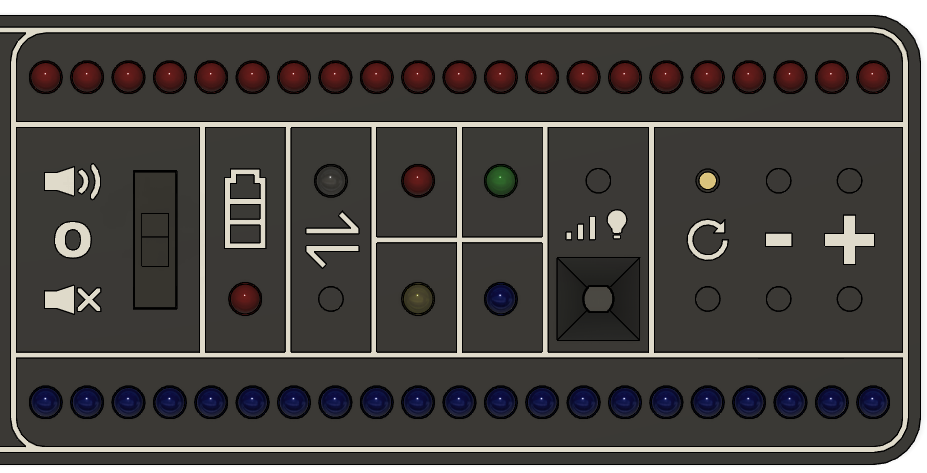
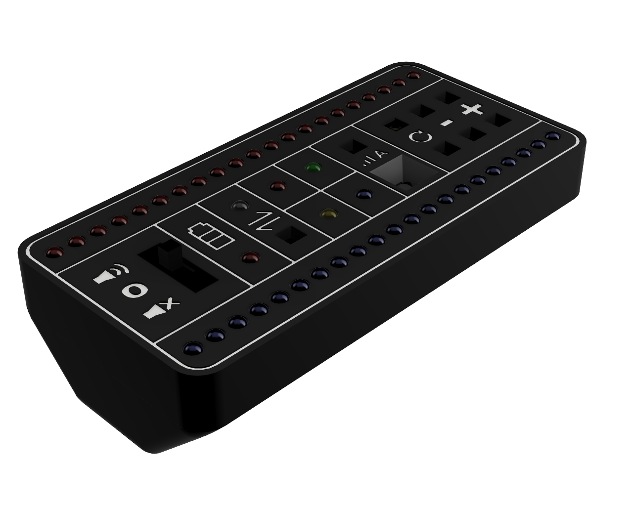


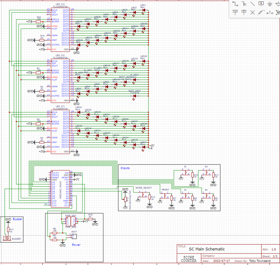
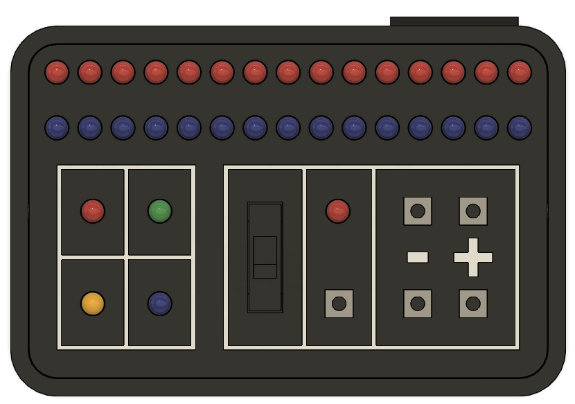
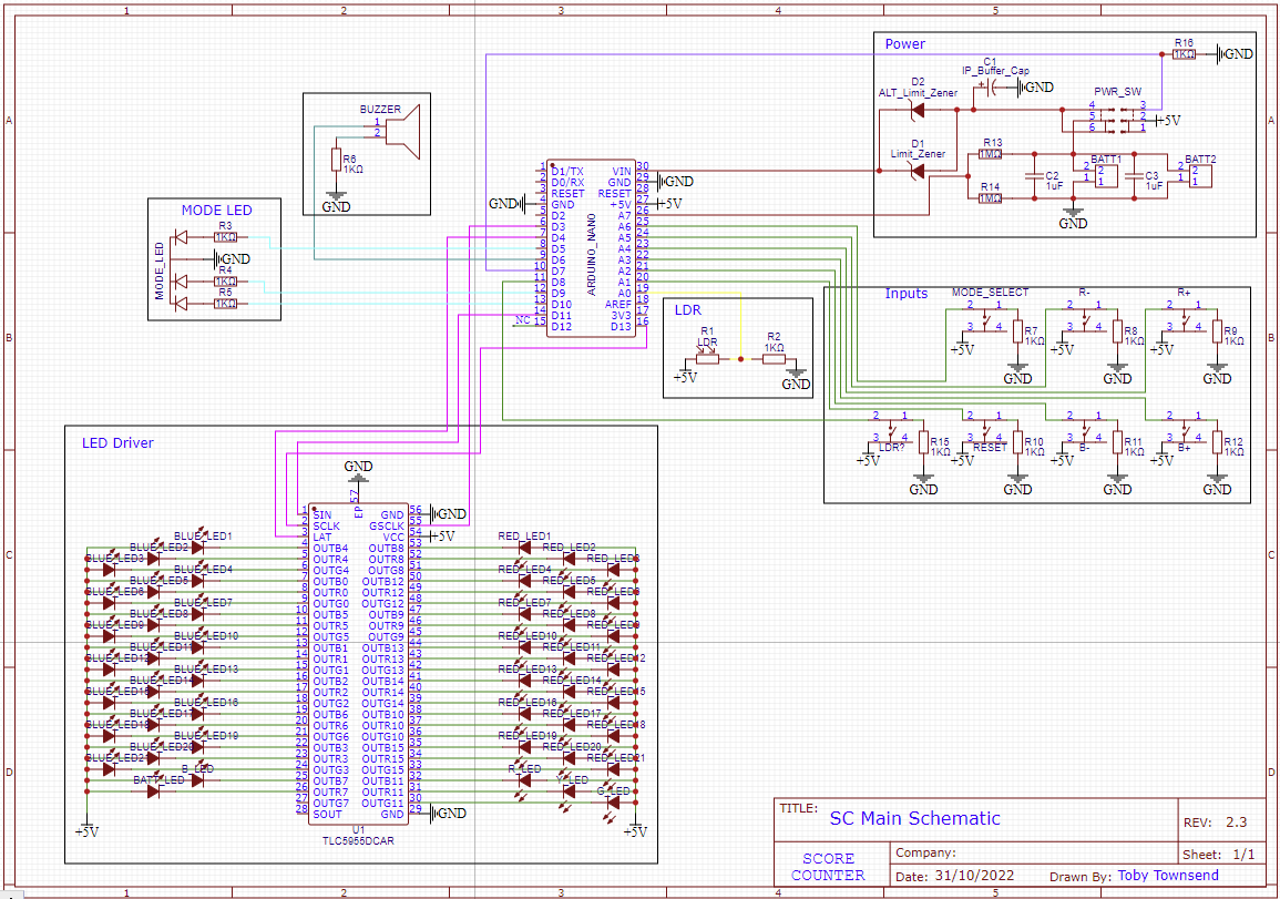
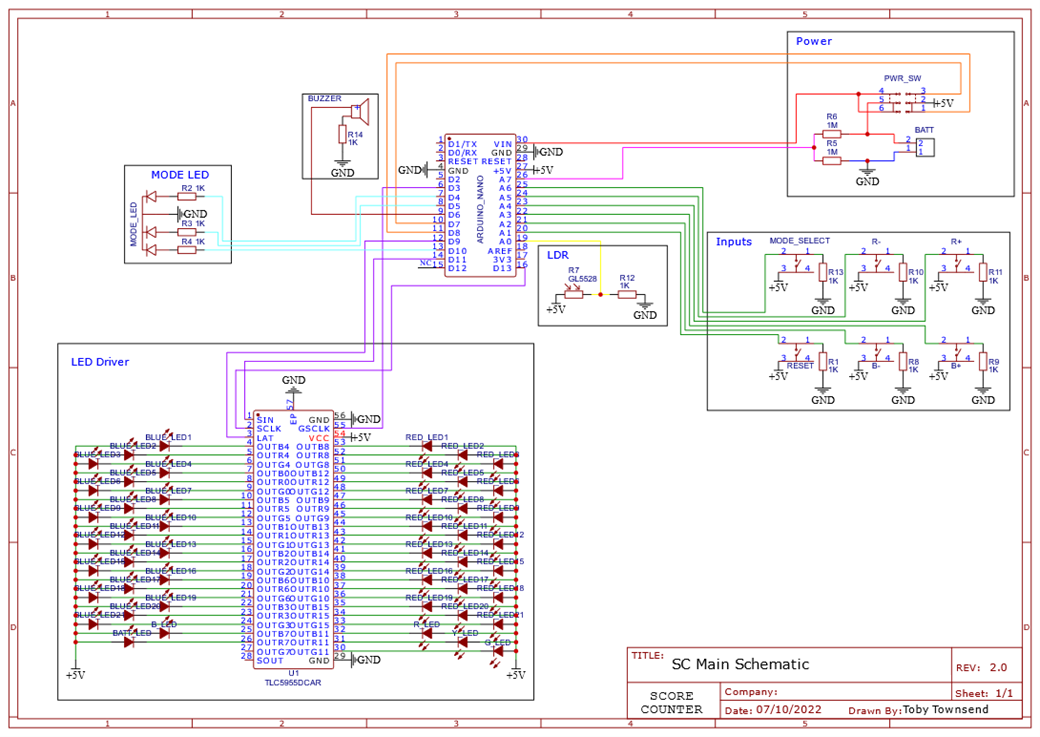
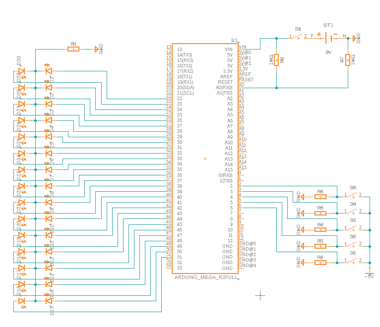

Comments