

Hardware components | ||||||
_qjmsadMGOi.jpg?auto=compress%2Cformat&w=48&h=48&fit=fill&bg=ffffff) |
| × | 1 | |||
 |
| × | 1 | |||
| × | 1 | ||||
| × | 1 | ||||
| × | 1 | ||||
| × | 1 | ||||
Software apps and online services | ||||||
 |
| |||||
 |
| |||||
 |
| |||||
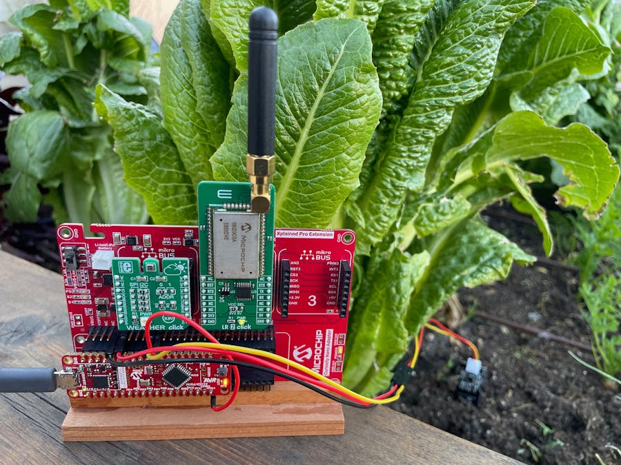
Water conservation has become increasingly important for farms in the southwest, as more and more restrictions are enacted to protect the Colorado River Basin. This project began as a Capstone project at Arizona State University in partnership with Microchip Technology with the goal of creating a cost-effective, low-power solution for a local community garden that wanted to better manage water usage and monitor soil conditions throughout their plot. The growing beds were too spread out to benefit from WiFi® access and the sensor nodes needed to be battery-powered and long-lasting. This solution would need to help optimize irrigation schedules and take into account weather conditions as well as the soil's local variability.
Picking a MicroOur group originally settled on the ATtiny1627 for our microcontroller (MCU); this post extends that original version and replaces the ATtiny with a newer part, the AVR64DD32. Both of these boards are perfect for low-power applications due to their multiple sleep modes and independent peripherals that facilitate gathering sensor data while allowing the MCU to sleep most of the time.
Even Lower PowerLoRaWAN is ideal for this application, where we can trade off latency in delivering data for a much longer battery life. Soil doesn't dry out or become saturated in milliseconds, so there is no need to send data more often than the 3-5 minute interval recommended by The Things Network. Because most of the power budget in the project is spent during the transmission of the LoRa packets, by reducing how often data is sent and thoughtful formatting of the payload, we minimize power costs without sacrificing important data.
II. Getting StartedAssemble the NodeDownload the AVR64DD32 CNANO Hardware User Guide located here, and the Curiosity Nano Schematichere.
Pull up the Curiosity pinout mapping on page 36 of the user guide as it will be helpful while assembling the hardware.
On page 1 of the schematics document, notice that printf support (Serial/ CDC port) will be enabled over PD4 and PD5. We will need a separate USART Tx and Rx for the LoRa module, and looking at the Curiosity Pin Mapping above, we see that PD4 and PD5 are used on Mikroe busses 1 and 3. This means that our Mikroe LR2 Click LoRa module will need to go on bus 2.
To initialize the LR2 we need to be able to reset the module, but the RST pin on bus 2 connects with (PA1) on the microcontroller. The parentheses indicate that PA1 and PA0 share the port with an external high-frequency oscillator module. The external oscillator offers significantly more accurate timing than the internal oscillator, but we don't need it for this project. However, to remove excessive capacitance on the lines and reduce signal contention, PA1 and PA0 are disconnected on the CNANO by default.
There is a helpful guide on how to connect these pins in the Hardware User Guide, but a quick and clever solution for this project is simply to use another GPIO pin and connect it to PA1. There are plenty of extra GPIO pins, so we will place a jumper between PA1 and PD1 and then use PD1 to reset the LoRa module.
Lastly, the analog input for the capacitive soil moisture sensor will be PD2. We can connect the ground (black) VCC (red) and the analog out (yellow) on the sensor as pictured in the photo. The end node hardware is set up; the next step is setting up the software.
Download the project here.
Open with MPLABX version 6.00 or newer, and connect the CNANO over USB.
We will need to calibrate our off-the-shelf moisture sensor first. Later these settings can be made specific to your soil and plant needs, but for brevity, we can begin with the upper and lower bounds for our measurements, (i.e., test in dry air and in a cup of water).
Open the application.c file, and change the initial state to TEST_MOISTURE.
Place the sensor so it is suspended in dry air.
Start the Data Visualizer. For printf support, we will use
- Baud Rate of 9600,
- Char length 8 bits,
- Parity None, and
- Stop Bits 1.
Click on the "Send to terminal" option to start the Data Visualizer.
Make and Program the device.
When the program starts, you will prompted to press the button to generate a new ADC read.
Take a few dry air samples. Our samples roughly measured 3000 (IN_MAX), so this is 0% moisture value.
Next, set the sensor in the cup of water; the water should be filled to a level below the line on the sensor. Let it sit for moment, then take a few readings. In our case, we measured roughly 1400 (IN_MIN), and this becomes the 100% moisture value.
Since the charging of a capacitor is non-linear, it is not possible to do an exact mapping to a percentage using this method, but we can identify ranges of what would be considered too wet, too dry, or ideal soil moisture. This is a good resource if you are interested in learning more about the sensor.
Now add your values to the project. Open the application.h file and edit the following definitions with the values you observed. Calculate the conversion percent as shown.
With the end node calibration complete, it is time to move to setting up a LoRaWAN.
Register an Application on The Things Network (TTN)If you haven't already done so, you will need to set up an account on TTN. The community edition is free for fair use. Sign up here to create a Things ID.
After setting up your account, navigate to your console and click on Go to applications.
Click Create application, and follow the instructions to create your application.
Next, set up the payload formatter. If you are already familiar with how to format LoRa payloads skip ahead, but if not, here is an explanation:
Bit Packing, aka Binary EncodingLoRa messages get encoded on radio waves. They are robust against noise and can travel long distances but to ensure good battery life and fair use of the gateway channel, packet size is limited for LoRaWAN. This is where binary encoding comes into play. Consider it would take 24 bytes to send the following JSON string:
{ "Temperature": 20.64 }If the field name is removed, the string is reduced to 5 bytes: 20.64.
But this can be reduced further by expressing 20.64 as 2064 and later dividing that value by 100 after receiving the packet. This brings the payload down to 4 bytes.
Even further reduction is possible if the value is converted to a hex string. Expressing 2064 as 0x0810 means only 2 bytes are needed for the payload.
Uplink Payload FormatterIn this project, we are sending four values: temperature, humidity, moisture, and pressure. The temperature measured will be between -127 and 128 °C so temperatures can be represented by a single byte. Humidity, moisture, and battery level will all be percentages between 0 and 100; so they also only require one byte. We express our pressure measurement in hPa which typically ranges from 950 hPa to 1050 hPa. Since this range is less than 255, a single byte is all that is needed because during the encoding process, we can subtract 900, and then here in the application, add 900 back to the result once it is received.
To set up the application payloader, expand the <> Payload formatters section and click on Uplink.
Under Setup, select the Custom Javascript formatter option.
Replace the default code for the decodeUplink() function with the following snippet:
function decodeUplink(input) {
    var data = {};
    data.temp = input.bytes[0];
    data.humidity = input.bytes[1];
    data.moisture = input.bytes[2];
    data.pressure = (input.bytes[3] + 900);

    return {
      data: data
    };
}
Now that the application is set up, we can add our end node to the LoRaWAN.
Setting Up An End DeviceThis tutorial will demonstrate the OTAA (Over The Air Activation) method of joining TTN; should you need it, ABP (Activation By Personalization) registration is also provided at the end of the tutorial. The two methods have different ways of handling the security keys which are used to encrypt the payload as it travels from the end device to your application. For OTAA, the security keys are dynamically allocated by a join server. For ABP, keys are statically allocated when the node is registered and then stored in the module's EEPROM. Unless there is a very good reason to use ABP, TTN recommends that all nodes use the OTAA method.
Both methods are supported by this project's code base. ABP can be very helpful when testing your project. We used it for example, to troubleshoot join errors which led to realizing that we needed to increase the distance between our gateway and end device, and adjust our data rate.
OTAA End Device RegistrationFrom the application Overview, click Register end device:
To set up your end device with TTN, we need to know the RN2xx3 module's hardware identifier, HWEUI. To get that, return to MPLABX and open the RN2xx3.h file. Make sure that the activation method for OTAA is defined and ABP is commented out.
Open the application.c file, and change the state machine's initial state to REGISTER.
Build and program the device, then use Data Visualizer to view the serial output. When the program first runs, the HWEUI and LoRaWAN specification used will be shown in the console. Copy the HWEUI which will be used in the next step.
Return to the Register end device page on TTN and select the Enter end device specifics manually option. Choose your frequency plan based on your location, then enter the LoRaWAN specification from the previous step. In the Provisioning information, enter all zeros for the JoinEUI field, then hit confirm.
This will take you to the section where we can paste the HWEUI copied earlier. Paste your HWEUI into the DEVEUI field. Then generate an AppKey and give your end device a helpful name or use the auto-generated ID. Click on Register end device.
We can copy the application payload formatter to the device by clicking on the Payload formatters button. Again, select Custom Javascript formatter for the type, and hit the Paste application formatter button.
Click on save changes.
Note: if you later make changes to the type and format of your data this is a very helpful page, as you can test how the payloads will be decoded.
The end device is now registered with TTN. Next, we will add the generated key to the code so that it can be loaded into the end device's EEPROM.
Update the Project with Your HWEUI and Generated AppKeyOpen the RN2xx3.h file in MPLABX, and scroll to the HWEUI and AppKey definitions. These are the two fields we will update.
Return to TTN, and make sure you are on the end devices overview page. In the activation information section, click on the copy to clipboard icon and paste the DevEUI into the HWEUI field in the RN2xx3.h header file. Paste the AppKey into the AppKey definition in the header file.
If you already live within 2 km of a public gateway, you may be able to use it. To check if there is a nearby gateway, enter a location here: https://www.thethingsnetwork.org/map If so, you can jump to section IV. Test on TTN.
If not, this tutorial will cover adding your own Basic Station gateway to your LoRaWAN. In this project, we are using the RAK2245 PiHat with a Raspberry Pi 4B. We are running the Pi in headless mode and the gateway as a docker container, using Xose Pérez's excellent docker image.
Set Up Raspberry PiFlash Raspberry PI OS Lite (64-BIT) onto an SD Card using Raspberry Pi Imager or similar imaging software.
In advanced options (click on the gear image), you can choose to set your hostname to something helpful, like basic-station; make sure you enable SSH and Configure your wireless LAN. You can choose password authentication or public-key authentication whichever you prefer.
Write the image, then remove the card and insert it into the slot on the Pi. Make sure that your RAK 2245 is properly set on the 20-pin header, and that you have securely attached your LoRa and GPS antennas.
SSH into the Pi and Prepare the GatewayPower up the Pi with the new OS loaded on the SD card. Open a terminal window and ssh into the device using the hostname that you set.
ssh pi@basic-station.localYou will need to accept the authenticity of the host by typing yes and enter the password.
Next, we need to update and upgrade the OS. In your terminal type:
sudo apt-get update && sudo apt-get upgrade -yThe concentrator uses SPI, so we need to enable the Pi to use it. This can be done with the Configuration Tool.
sudo raspi-configThis will open a dialog. Down arrow and hit enter on Interface Options.
Down arrow and select SPI.
Select Yes.
Right arrow and hit enter on Finish.
Next we need to install Docker, at the command line type:
curl -sSL https://get.docker.com | shConfigure Docker to run on boot.
sudo systemctl enable dockerFor convenience, you can choose to add your user to the Docker group to manage it without sudo.
sudo usermod -aG docker ${USER}Reboot the system, and check that Docker was installed and runs at boot with:
docker --versionNow add Docker compose to the system to make it easier to manage containers with configuration files.
sudo apt install -y python3 python3-dev python3-pip libffi-dev libssl-dev
sudo pip3 install docker-compose
docker-compose --version
Next we need to register the gateway with TTN, but to do so we will need the gateway's unique identifier, an 8 byte value, aka EUI. To get your EUI, type:
cat /sys/class/net/eth0/address | awk -F\: '{print toupper($1$2$3"FFFE"$4$5$6)}'Copy the 8 byte EUI then open your TTN console.
Click on the Gateways tab and click on register your gateway:
Paste the EUI into the Gateway EUI field, and click on Confirm.
Select Register authenticated connection. Add a human readable ID and name. Select your Frequency plan. Select Require authenticated connection, but deselect the option to auto generate API keys for CUPS and LNS. Finally, click on Register gateway.
Click on the key in the side panel and click on add API key.
Give your key a name. Grant individual rights, and select "Link as Gateways to a Gateway Server for traffic exchange, i.e. write uplink and read downlink." Click on Create API key.
Download the keys, you will need them for the docker compose configuration.
SSH back into your Pi if you are not connected to it already. Create a docker-compose.yml file and paste the following into it. Update the file to include your GATEWAY_EUI, TTN_REGION, and TC_KEY from the previous steps. Make sure you preserve the indentation. Save and close the file.
version: '2.0'
services:
  basicstation:
    image: xoseperez/basicstation:latest
    container_name: basicstation
    restart: unless-stopped
    privileged: true
    environment:
      MODEL: "RAK2245"
      GW_RESET_GPIO: "17"
      SPI_SPEED: "2000000"
      GATEWAY_EUI: "Enter you Gateway EUI here"
      TTN_REGION: "Enter your frequency plan here"
      TC_KEY: "Add you downloaded API key here"
With the configuration added, pull the basic station image with:
docker-compose pullOnce the image is downloaded, bring up the service with
docker-compose upWhen concentrator has started and the keys have been matched, a secure channel is created. Look for "Concentrator started" in the log displayed live in the terminal.
Once you have confirmed that your basic station has connected, we will stop the container and set it up to run in the background.
Hit Ctrl+C, then type
docker-compose downSet it up to run in the background.
docker-compose up -dReturn to your browser. You should see that the gateway is connected and receiving status updates.
Now it is time to test your LoRaWAN with TTN.
Return to the application.c file, and change the state machine's initial state back to INIT.
Start the data visualizer again, and re-program the device.
When the application starts, the modules will be initialized. Press the button to start the join procedure.
The channel frequency plan set up will take about ten seconds to finish, afterwards you should see the following events.
For this project, the node sends new data every three minutes. Once per day, it sends the data as a confirmed payload as in this first transmission. Confirmed messages require an acknowledgment from the network, but also consume airtime on the gateway and extra battery life for the node. So the remaining 479 messages each day are sent as unconfirmed messages.
As a convenience, this project sends all confirmed messages on port 10 and unconfirmed messages on port 11. You can see in the image below that after starting the node and sending the first unconfirmed message, subsequent unconfirmed messages are sent to the application every three minutes on FPort 11.
For our initial field tests, we placed our gateway indoors, near a window on the third floor of our building and about 12 meters above the ground. We first placed our node 130 meters away. At this distance with the node resting on the ground, we had no problem joining and could easily transmit and receive packets.
So we moved further away to ~450 meters, and found that with the increased distance, our node benefited from being about a ½ meter above the ground. We had line-of-sight visibility with the gateway, but at this location, there was now a large, 5-meter berm that was in the Fresnel radius of our radio waves. Once we moved our node a half meter above the ground, we again had no problem transmitting and receiving.
Next, we tested the project at 517 meters.
The image below shows a log from transmitting at this range, and demonstrates the value of using an adaptive data rate. At 9:19:45, the node sends a join request uplink. From the log, it can be seen:
- The uplink was sent using data rate 0, which uses spread factor 10 and bandwidth 125 (SF10 BW125).
- It arrived at a level above the noise floor: SNR: 7.75 (positive SNR values are above the noise floor)
- It is relatively weak signal, RSSI: -102 (stronger signals are closer to 0)
Looking at subsequent uplink and downlink records, it can be seen that with each acknowledgement, the node tries a better data rate. By 9:22:11, the node is now sending at the best possible data rate, dr 3 which uses SF7 BW125. This is fastest data rate that can be used, which means that the node is now optimally conserving power. This example also shows that although the signals are arriving below the noise floor (SNR: -0.25), the chirp spread spectrum technique still allows the data to be reliably decoded.
VI. Set up IntegrationsDatacake works very well with TTN. You will need to set up a free account which allows you to have two devices on your network for free.
There is an excellent tutorial here on how to connect Datacake to The Things Stack.
Once you have completed the set up, you will want to add a specific formatter for the project's data. Click on the Configuration tab.
Scroll down to the Payload Decoder section.
Replace the Decoder function with the following:
function Decoder(bytes, port) {
    var decoded = [];


    decoded.push({
        "field": "TEMPERATURE",
        "value": readInt16LE(bytes.slice(0,1)),
    });

    decoded.push({
        "field": "HUMIDITY",
        "value": readUInt16LE(bytes.slice(1, 2)),

    });

    decoded.push({
        "field": "SOIL_MOISTURE",
        "value": readUInt16LE(bytes.slice(2, 3)),
    });

        decoded.push({
        "field": "PRESSURE",
        "value": (readUInt16LE(bytes.slice(3, 4)) + 900),
    });

    return decoded;
}

/* ******************************************
 * bytes to number
 ********************************************/
function readUInt16LE(bytes) {
    var value = (bytes[1] << 8) + bytes[0];
    return value & 0xffff;
}
function readInt16LE(bytes) {
    var ref = readUInt16LE(bytes);
    return ref > 0x7fff ? ref - 0x10000 : ref;
}
Here is an example of our dashboard, where you can see that over the course of the morning, as the sun came up, the temperature rose, while the humidity decreased. Around 10:00 am the garden was watered, and the soil moisture rose to 100%.
In case you need it, these instructions go through how to set up an ABP join. From the application Overview, click on the Register end device button:
Select the following:
- Enter end device specifics manually
- Frequency plan 902-928 MHz, FSB 2,
- LoRaWAN Specification 1.0.0.
- Change the Activation mode to Activation by personalization (ABP)
- Increase Rx1 delay to 5 sec.
Scroll down to the Provisioning section, and click on generate for each of the following:
- DevEUI
- Device address
- AppsKey
- NwkSKey
You can give your device a human readable ID, if desired..
Don't worry about copying these down at the moment, you will be able to access them after you register the device. Click on Register end device.
Thanks for reading about how to build an 8-bit, LoRaWAN sensor node for Agricultural IoT. Happy transmitting.


_M6kErcYJ84.png?auto=compress%2Cformat&w=40&h=40&fit=fillmax&bg=fff&dpr=2)
Comments