Since the beginning of year 2020 the world have changed a lot due to covid-19 virus outbreak. People´s lives have changed a lot and everyone has in some way encounter the virus.
Due to the covid-19 virus it´s nowdays very important to take different messueres to reduce the risk of spreading the virus. This can be done in many ways and one of them is to avoid using buttons, switches and door handles in public areas.
But this is for the most part impossible because every door has a door handle and many doors and elevators requieres the use of button or swith. I have therefore came up with a solution where people can use solutions which includes buttons and switches without using their hands.
How it worksNote! This is a prototype which is scaled down to make possible to print it with a 3D-printer. The model is about five times smaller then what it schould be.
To reduce the spread of covid-19 there are many meassures that can be taken. One is meassure is to avoid toucing handles, switches and button in the public.
I have therefore came up with a solution to use doors with automatic door openers and other stuff like elevators without touching any thing with your hand.
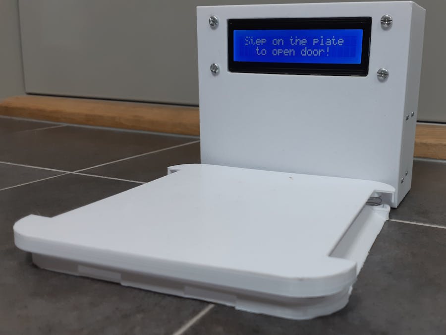
By stepping on a plate made of 3D-printed plastic it actuates a built in push button which actuates a relay that controls a door or a elevator depending on the user´s choise.
This works because most doors/elevators that uses buttons have a voltage that is used to tell if the door should open or close depending on the state of a button. By instead using a relay instead of a button you can control doors and elevators without using the button at the door.
My solution consist of a base which have a push button mounted in it. It also have four springs which holds a plate. On the side of the base I also mounted a enclosure for a LCD display, a relay, two LED´s, an Arduino, a custom made cicuit board for the lcd and a SD-card reader/writer.
The base is placed on the floor and by steeping on the plate it´s pushed down and actuates the button in the base. The signal goes to an Arduino Nano Every which processes the signal.
The Arduino then sends out a signal to a custom made cicuit board which controls a 20x2 LCD display. The LCD then writes out the message "Make sure to keep your distance (2m)". After 5 seconds it displayes the messege "Wash your hands regularly!".
The Arduino then sends a signal to a NPN transistor which controls a relay. This relay can control external signals which can control automatic door openers, elevators, gates and other stuff that is some way controlled with a button or a switch.
There is also a red and a green LED which makes it easier to see when the door opens or closes. The red LED is lit when the door is closed and the green LED is lit when the door is opened.
ConstructionThe base is made of PLA plastic with a 3D-printer. The base have two ramps in the front and the back to make it easier to come up to the plate, especility for peoples in wheelchairs. In the middle of the base there is a hole for a pushbutton and a channel to hide cables.
On two sides (left and right) there is openings to let water out after rain if the device is placed outside.
The plate on top of the base is just a plate with four mounting holes for four springs. It also has two cut-out´s for the two ramps on the base.
There is also a box which holds the electronics. It holds the Arduino, relay, LCD, the circuit for the LCD and a 9V battery holder. Everything but the 9V battery holder is mounted with screws and nuts. The battery holder is glued to reduce the amount of screws that are seen. This also makes it harder for unauthorized persons to disassemble the unit.
ElectronicsThe electronics is based around an Arduino Nano Every. It´s suited for battery power and it´s small and powerful with many inputs and outputs. The Arduino Nano is fitted into a "shield" with screw terminals to make it esier to connect wires and to avoid unnecessary soldering. This also makes it esier to upgrade, change or remove parts if needed without soldering.
A SD-card reader/writer like shown in the schematic is connected to the Arduino Nano via the screw terminals.
The button placed in the base is also connected to the Arduino like shown in the scematic. It also has a 10K pull-down resistor to avoid random signals to the Arduino.
A second button is also connected to the Arduino. This buttton is used to turn off the Arduino and it´s data logging. This button needs to be pressed before the Arduino is powered off to make sure the data logging file closes correctly.
A relay is also connected to the Arduino. It´s used to control what ever device you want to control. It has a BC547B transistor which takes the signal from the Arduino and switches the transistor on and amplifies the signal to power the relay. The relay also has a diode to release the inductors charge when the relay is powered off.
To control the LCD I have built a custom made circuit board which is powered by the 9V battery. It has a ATMEGA328P to control the lcd and a voltage regulator with smothing capacitors to provide power to the circuit. There´s also a 16MHz crystal and two 22pF capacitors to make the clock for the IC. There´s also a 10k trimpotentiometer to adjust the contrast of the LCD and some female headers to connect the LCD.
The cicuit for the LCD is connected with a single wire to the Arduino for communication.
All of the programming is explained in the code.
I have during my programming used a libary for the LCD display and one for the SD-card reader/writer, both are built in the Arduino IDE.
Tools and materialsI have used simple tools like cutters and a wire stripper. I have also used a soldering iron to make the circuit boards. I recommend using a helping hand while doing the soldering but it´s not necessary.
I also used a 3D-printer with PLA filament.
The benefits of the solutionThere are many benefits of the solution. The most obvius benefit is that there is no more need to use your hand to press a button or a switch to actuate a elevator or a automatic door opener. You simply step on the plate and the door openes.
There are also other benefits like doors and elevators gets more accseble and easier to reach and use especialy for people with some form of disability reduction.
The built in LCD-display also helps to reduce the risk of spreading the virus by informing and reminding users to keep a 1,5-2 meters distance to each other and also wash hands regularly.
Thanks to the built in SD-card reader/writer the owner can monitor the amount of visitors or users. The owner of the device can there for use that data to warn other visitors.
This way of using this solution, espacilaty with doors is also more energy-efficent. This is because the door needs interaction from a human and therefore does not open by passing people which lets much heat in or out of the building.
This solution is also very easy to install. It does not requiere any digging or prepariions to use it. It´s like a mat and can placed in front of most doors. It can also be used in combination with already exsisting buttons and does therefore not need to disassemble already exsisting solutions.
The message on the LCD display can easly be changed to whatever the owner wants.
About meMy name is Tim and I´m fourteen years old. I live in Sweden and I have a big interest in building stuff with electronics and other things as well as with 3D-printers and with my CNC-router.


Comments