

Hardware components | ||||||
 |
| × | 1 | |||
| × | 1 | ||||
| × | 1 | ||||
 |
| × | 1 | |||
| × | 2 | ||||
| × | 2 | ||||
| × | 1 | ||||
| × | 2 | ||||
 |
| × | 1 | |||
 |
| × | 1 | |||
 |
| × | 3 | |||
 |
| × | 1 | |||
| × | 1 | ||||
| × | 1 | ||||
Software apps and online services | ||||||
| ||||||
| ||||||
Hand tools and fabrication machines | ||||||
 |
| |||||
Too many persons get injured (or worse) due to icy conditions, in the US alone there are tens of thousands of injuries involving ice, sleet, or snow. Typically, the city or state is responsible for ensuring public roads are safe, but responsibility shifts to you at the start of your own driveway. Thus, you need to ensure it is safe yourself. You can, of course, salt or sand your icy driveway manually, just as you can mow your lawn, vacuum your home, or wash dishes by hand. While curing your driveway from ice might be enjoyable for some, it’s tedious for others. If you find yourself in the latter group, read on for a solution!
Meet Ice Beat-Le, a symphatethic looking rover designed to combat ice by spreading salt, sand, or other suitable materials on your driveway or path. The rover is driven by six wheels and navigates using infrared (IR) sensors to lock onto an IR beacon.
For the rover’s MCU, I selected the Particle Photon 2 because it's versatile, powerful, yet easy to work with. The IR beacon currently uses a Propeller Activity Board from Parallax because it includes an onboard D/A chip. If another Photon 2 had been available, I would likely have redesigned the beacon circuit and software to use Pulse Width Modulation (PWM) instead of the D/A chip.
Although the 41 cm (16") long rover looks complex due to its electronic components, motors, servo, and mechanical parts, it is actually quite straightforward, even minimalistic. There are no unnecessary bells and whistles - the rover does exactly what it’s intended to do, nothing more, nothing less.
However, the journey of designing and building the rover involved overcoming numerous technical challenges. Before I chose to focus on IR, I had looked at navigation with help of Bluetooth, RFID, camera, QR-codes, LIDAR, and GPS/GPS-RTK. All of these have their own pros and cons from technical, programmatic, and cost point of views. Furthermore I needed to find a suitable rover battery (my old robot vacuum involuntarily donated two to me), design, 3D-print, and test the spreader mechanism and enclosures, etc.
Navigation
Navigation is achieved using an IR beacon transmitting a 38 kHz IR signal of varying intensity, utilizing the Sony protocol—the same used by many TV remote controls. Unfortunately, the IR receivers ("eyes") on the rover can only detect whether a modulated IR signal is present, not its intensity. This limitation makes it very challenging to navigate using a constant IR signal alone, as the rover wouldn’t be able to determine if it's to the left or right of the beacon’s beam.
To overcome this issue, I adopted a solution that involves varying the intensity of the IR signal. By modulating both the brightness and pulsing of the beacon, the rover measures how frequently it detects the IR signal, allowing it to determine its orientation relative to the beacon.
To generate both the modulated (pulsed) IR signal AND the varying brightness, two different signals are fed into the LED at the same time. The positive leg of the LED connects to an I/O pin, where the code is sending it pulses by turning it on and off 38000 times per second. The negative leg of the LED connects to a D/A-pin, which is changing its voltage output from 0V (full brightness for the LED) to 1.6V (nearly off). Why is 0V bright and 1.6V dim? Because this is where the negative leg is connected. The result is that the “Sawtooth”-like output of D/A is subtracted from the 3.3V pulses from the I/O pin:
The rover counts how often each IR sensor detects the beacon's light. If one side detects fewer pulses than the other (indicating that side is farther from the beacon), the rover turns in the opposite direction. E.g., in the driveway sketch further above, the left sensor receives less light than the right, and thus the rover needs to turn right. Since IR signals can be slightly erratic due to external interference, each receiver uses a moving average to stabilize readings.
Sanding/Salting
In the name of simplicity, and instead of inventing a salting mechanism needing a strong motor, I decided to use a force available to all of us for free → gravity. Sand, salt, or any other suitable material is poured into the container which has a hole in the bottom. To avoid that the sand falls away directly, a servo-controlled lid is opened or closed within the main control program. The sand falls down on the spreader which spreads it over approximately half a meter in width as the rover moves forward. If large particles are used, there's a risk of them clogging the container opening. However, as the rover doesn't have differential steering, and also as its minimum working speed is quite high, it twitches a bit when alternating between driving, turning, and coasting, and I found out that this leads to that potential clogs are easily dissolved.
Enclosures
- The rover electronics enclosure consists of a dome top and a bottom with openings for the wires and fastener screws. It was challenging to get proper tolerances as the wall on the bottom needs to perfectly fit into the grove on the dome top. As the dome top took over 5 hours to print, I only printed one, and then adjusted the bottom, which was good enough first with iteration 7.
- The IR-beacon enclosure consists of a case and a lid which fit perfectly together.
Assembly Instructions
- Assemble the rover itself according to instructions, my rover came preassembled as it was a used one.
- 3D-print the different components, most of them do not need supports if they are rotated properly. For most parts I used an infill of 10-20 %.
- Feel free to redesign the components according to your platform and needs. Remember to add tolerances when designing pieces that need to fit together!
- Wiring schematics are found in a separate chapter.
I've been designing 3D-printable objects for a few years, mainly with Windows 3D-builder and later TinkerCad. Both have a shallow learning curve, but are in my opinion quite limited in functionality and how easy it is to later change dimensions of part of an object.
For this project I quickly saw that I'd need a parametric modeling software, and decided I'll try Autodesk Fusion. As a true engineer (which I'm not!), I plunged in without first learning the basic functionality, and just started to design the most important but in the end also most challenging part first, the spreader, and learned by doing, successing, and failing. With hindsight this was not the optimal way, watching a few tutorial videos would most probably have been very wise and time-saving in the long run. As a result, I'm sure not everything is designed the "proper" way, but hey, if the fire is put off, does it matter how it was put off...?
Once the spreader was designed, printed, and tested, I started to think about the rest. Early on I decided I need to modularize. First of all, even if I have a big 3D-printer (420x420x500 mm), it would be near impossible to 3D-print the container and the whole supporting structure in one piece, Secondly, I wanted to be able to test one module at a time, and redesign the smaller module instead of the whole structure. This was a wise decision, as apart from the container, all the other parts needed many iterations because of tolerance issues, pure mistakes, or printing issues.
I would have saved a lot of time and material by creating a functional rectangular case for the electronic enclosure, but that would also have looked very boring compared to the black dome with yellow "insect eyes" sticking out, wouldn't it?
Rover Electronics
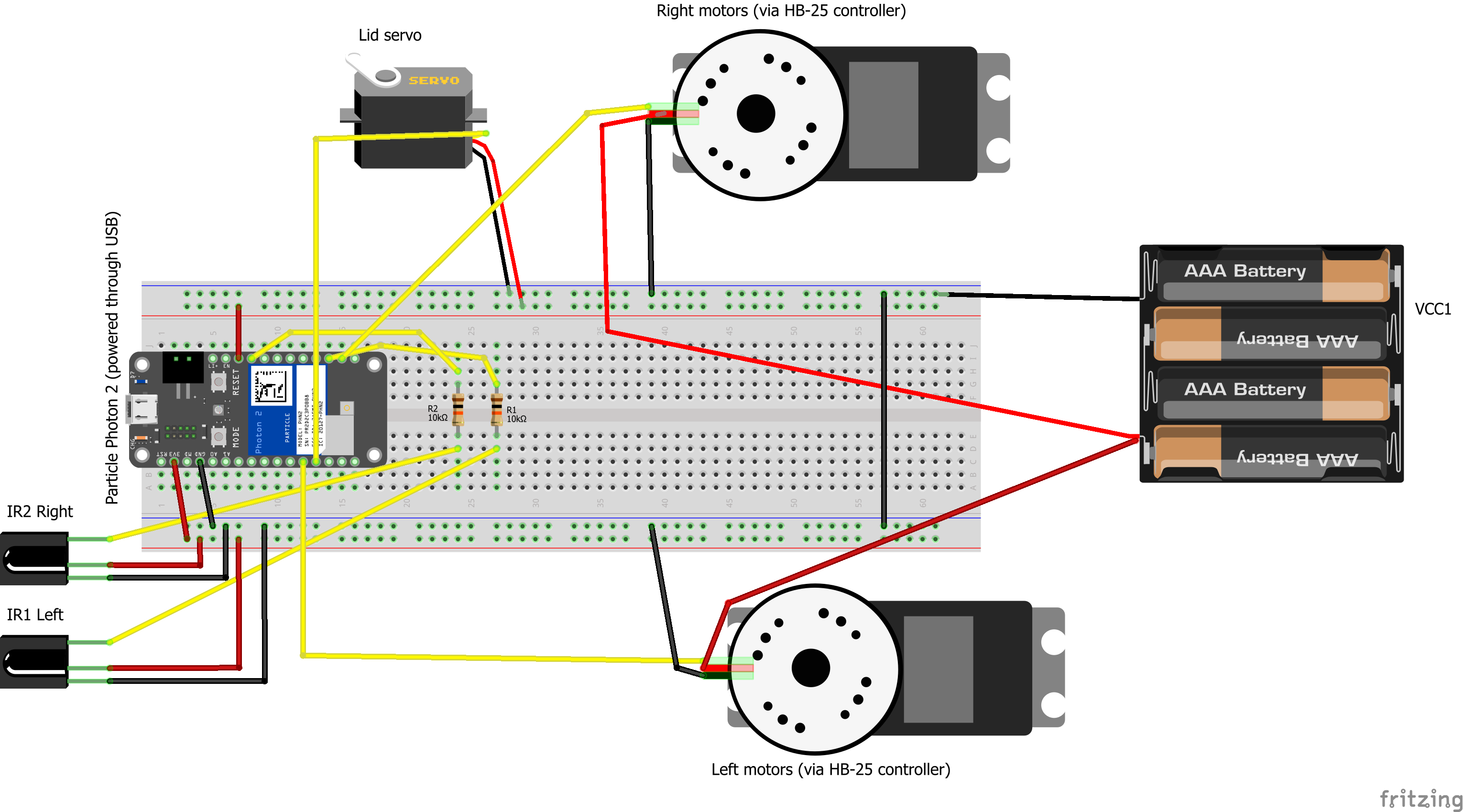
- Photon 2 connections
---------------------------------
| Photon 2 | To                 |
|--------- |--------------------|
| D15      | Left motor signal  |
| D1       | Right motor signal |
| D2       | Left IR signal     |
| D10      | Right IR signal    |
| D16      | Lid servo signal   |
| VUSB     | Lid servo power    |
---------------------------------- Fritzing diagram
- Close-up photo, do note that the lid controlling servo is left out of the photo for clarity, it is connected to VUSB and D16.
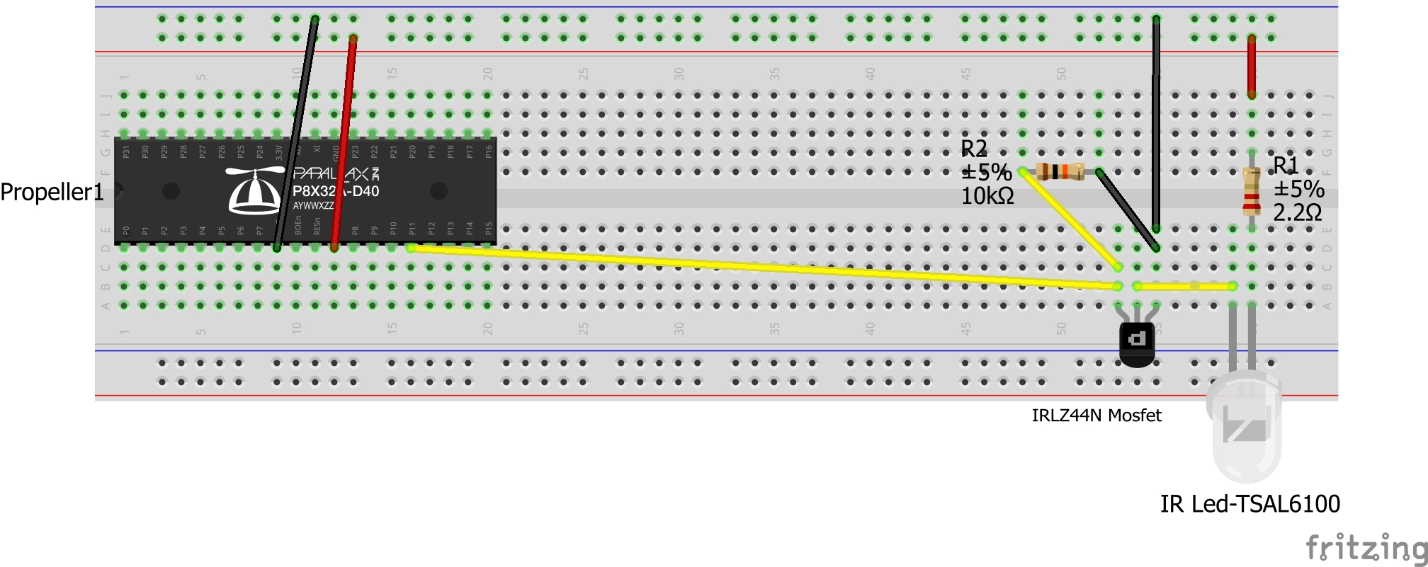
IR Beacon
- Fritzing diagram. In my setup I'm using the Propeller Activity Board as it has a D/A-chip.
- Close-up photo. To narrow the infrared beam a bit, the IR LED is equipped with a plastic straw enclosed in black electronic tape.
Below a description of the main functions.
IR Beacon
The beacon program is very simple, it pulses out IR light with a frequency of 38 kHz, in this case using pin 11 on the Propeller MCU. Every pulse is 3 milliseconds in length. The intensity is changed between nearly off until fully lit (330 = 3.3V).
// ------ Libraries and Definitions ------
#include "simpletools.h"
#include "abvolts.h"

// ------ Global Variables and Objects ------

int dimmer;

// ------ Main Program ------

int main() {

    da_init(26, 27);

    while(1) {
        for (dimmer = 0; dimmer < 160; dimmer += (10)) {
            da_out(0, (dimmer* 256 / 330));
            freqout(11, 3, 38000);
        }
    }
}
Photon 2
The function IR_read reads the IR sensors 96 times per loop and accumulates the pulses read per sensor. The higher the number is, the closer or more aligned the sensor is to the beacon.
// Read the IR sensors
// leftOut and rightOut are passed by reference
// They will be updated with the number of times the IR sensor was triggered
// The higher the number, the closer the sensor is to an object

void IR_read(int &leftOut, int &rightOut) {
    int leftIR = 0;
    int rightIR = 0;

    // Sample 96 times (16 * 6)
    for(int n = 0; n < 96; n++) {
        leftIR  += !digitalRead(LEFT_IR_PIN);                   // Read the digital value of the IR sensor
        rightIR += !digitalRead(RIGHT_IR_PIN);                  // Read the digital value of the IR sensor
        delay(1);                                               // 1 ms between samples
    }
    // Assign results to the provided references
    leftOut  = leftIR;
    rightOut = rightIR;
}- The function
drivedrives the rover by the speed received for each side. The motors are off when the value is 90, and as they need to rotate in opposite directions the given speed is added to 90 for the left motors, and subtracted from 90 for the right motors.
void drive(int left_speed, int right_speed, int time) {
    left.write(90 + left_speed);    // Move left motor forward
    right.write(90 - right_speed);  // Move right motor forward
    delay(time);                    // Delay selected time
}- The main loop (see full code) consists of reading the IR sensors, calculating a rolling average for each of them, and based on possible difference between the readings turning right or left. As the rover's minimum speed is too fast indoors and for testing, it is alternating between driving forward, coasting, or turning.
A YouTube video is found here, and a speeded up GIF-video below. As they show, the rover corrects its direction itself while twitching and jerking.
Issues overcome
As mentioned earlier, while the final result appears minimalistic, the journey to achieve it was neither simple nor straightforward. Indeed, there were several challenges and setbacks along the way. Finding a reliable solution for outdoor navigation took considerable experimentation - I had to acquire and test various IR LEDs and receivers extensively before finding an effective combination. Additionally, learning Fusion 360 from scratch, designing twelve distinct 3D-printed components, and printing numerous iterations consumed significant time and roughly one kilogram of filament, of which approximately 80% ended up as scrap.
How does therover perform?
The navigational part works much better than I could've expected. While the rover is not always driving in a straight line, nor did I expect it to, it is self-correcting and the light zik-zagging leads to better coverage when spreading material.
For testing the rover indoors, the motors are not optimal as the rover can't drive slowly. To solve this I programmed it to alternate between driving and coasting, leading to twitchy behavior. However, as mentioned earlier, a positive result is that possible container clogs are dissolved. For outdoors use the minimum speed is completely ok.
Also the spreader mechanism works better than I'd expected, after designing and 3D-printing a prototype for testing, the next version became the final. The middle ridge right under the container hole effectively accelerates sanding material to distribute quite evenly to both sides. The guard walls at each end was the only change between the prototype and final version. As the pictures show, the different surfaces are angled between 15 to 30 degrees to utilize gravity in an optimal way.
The seven components of the spreader mechanism, container, and support structures do fit quite nicely with each other. The twitchiness of the rover however leads to components getting a bit loose, so in a final installation they would benefit from being glued.
Future enhancements
This initial version of the rover isn't yet fully autonomous; for safety, it currently only moves when the IR beacon is transmitting. Presently, it moves forward and turns left or right as needed, but it would be relatively straightforward to add functionality enabling it to reverse its route or cover wider areas. Expanding the coverage could be achieved either by implementing a larger spreader mechanism or programming the rover to follow multiple parallel lanes.
To achieve full autonomy, adding bumper switches or distance sensors would allow obstacle avoidance, while integrating an odometer or a high-precision (centimeter-level) differential GPS would significantly enhance navigation capabilities - though these would add to the cost.
While the current maximum range is still untested, it is at least 10 m. To increase the range, an IR LED with narrower beam is expected to help. Changing a critical component like the LED or the IR receivers however requires thorough testing and possible redesigning of the circuit or program.
For permanent installations, the existing breadboard setup should be replaced by a custom PCB or at least a soldered protoboard. Additionally, the two separate battery systems currently in use could be consolidated into a single, higher-capacity battery for improved efficiency and runtime.
Final Conclusions
This Ice Curing Rover, affectionately called Ice Beat-Le, is a six-wheeled autonomous vehicle that spreads sand or salt on icy driveways, helping reduce winter slip hazards. At the heart of the rover I used the Particle Photon 2, whose powerful yet beginner-friendly platform made it easy for me to prototype, program, and control the robot’s complex behaviors with minimal overhead. Navigating via a modulated IR-beacon and using a gravity-fed dispenser controlled by a servo, the rover is a compact solution built with 3D-printed parts and off-the-shelf components. The Photon 2’s combination of real-time control, built-in connectivity, and versatility made it the ideal choice for this project - especially for balancing simplicity with performance. With a few additions, such as obstacle sensors or lane logic, the rover could easily evolve into a fully autonomous ice-clearing assistant.
While the road to some degree was bumpy and twitchy, it led eventually to the goal, and the ice is now beaten away!
IR Beacon

_t9PF3orMPd.png?auto=compress%2Cformat&w=40&h=40&fit=fillmax&bg=fff&dpr=2)


Comments