


Hardware components | ||||||
 |
| × | 1 | |||
Software apps and online services | ||||||
 |
| |||||
The thingSoC RS485 module is a simple way to create RS485 "wired" networks of Arduino compatible AVR microprocessors. The thingSoC RS485 module can either be used as a thingSoC Base (populated with sockets) or a thingSoC Expansion module (populated with pins or stack-thru sockets). In this example, we are using each thingSoC RS485 module as a standalone Base (populated with sockets) , and can plug other Expansion modules (ESP8266, RS-232, Ethernet, etc.) into the thingSoC RS485.
The thingSoC RS485 module includes a wide voltage range RS-485 transceiver chip, with a termination matching circuit. This allows the thingSoC RS485 to be strapped for either 3.3V or 5.0V operation, depending on what you need to interface with.
In this example, we use the DMXSimple Arduino Library from tinker.it/PJRC for the DMX-512 Master node, and DMXSerial from Mattias Hertel for the DMX-512 Slave nodes. Below is a photo of a simple test setup for DMX-512 (and other RS-485 protocols like Modbus or VMB).
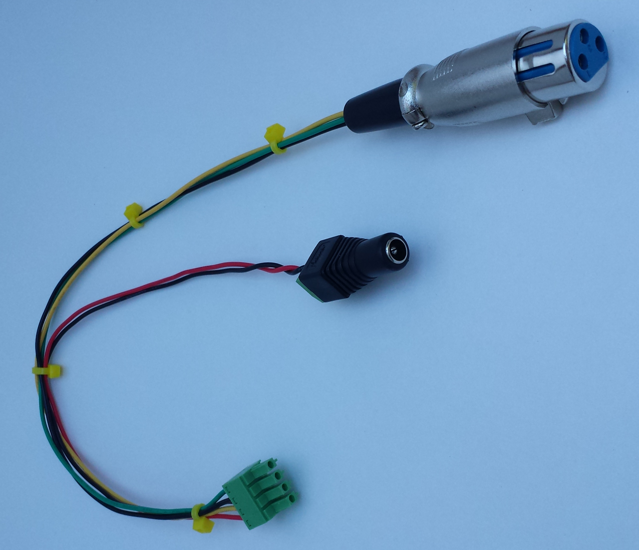
- The DC Barrel Jack is used to provide 5 Volt DC Power to the system, the power draw is minimal( < 300mA), and a USB outlet or charger can be used.
- The little "red" FTDI to RS485 breakout is used to monitor the RS485 transactions on the bus from either the host computer or protocol analyzer.
- TSOC_RS485 #1 is the DMX-512 "master" node and transmits on the bus. It also has a Methane Sensor (Methane Click) installed on it, and can monitor Methane levels in an area, and transmit that data on a DMX-512 channel. The Methane Sensor requires 5.0 V operation, so the TSOC_RS485 master is strapped for 5V operation.
- TSOC_RS485 #2 & #3 are DMX-512 "slave" nodes and receive on the bus. Each "slave" also has a dual (2) relay module (Relay Click) installed onto it, so that each node can control two different external devices using relays. They can each be assigned to different DMX-512 channels for control. The Relay Click requires 5.0 V operation, so the TSOC_RS485 slaves are strapped for 5V operation.
The DMXSimple Library is installed from the Arduino Library manager :
The DMXSerial Library is installed from the Arduino Library manager :
The DMX-512 "master" node and DMX-512 "slave" nodes use different programs. Open the tsoc_rs485_dmxMaster.ino sketch and upload it to the master node.
Open the tsoc_rs485_dmxSlave.ino sketch and upload it to the slave node(s).
The attached Master Sketch just cycles through the addressed DMX-512 channels, turning them on and off in sequence. This will ensure that you have all your wiring correct and that the setup is working for you.
Happy Hacking !


Comments