


Hardware components | ||||||
 |
| × | 1 | |||
 |
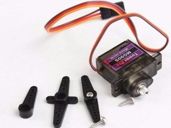
| × | 1 | |||
Software apps and online services | ||||||
 |
| |||||
 |
| |||||
Theremino team want to join the analog world (that of humans) with the digital world, and to do this, we have created a very simple system that's easy to use.
Our history can be found here:
http://www.theremino.com/en/contacts/the-theremino-history
We set the system so that the application program resides on your PC and the master is only an executor of commands received via the USB port.
This basic concept clearly divide the computing problems of data with those of the electronic circuits, sensors and actuators.
You do not need to learn another language, use the language that you use regularly.
This simple project to drive a servo at the same time has the goal of showing how easy it is and to do it.
The Thremino system give his peak in terms of performance when is connected natively with the modern Microsoft operating system like XP, Vista, 7, 8, 8.1 and 10.
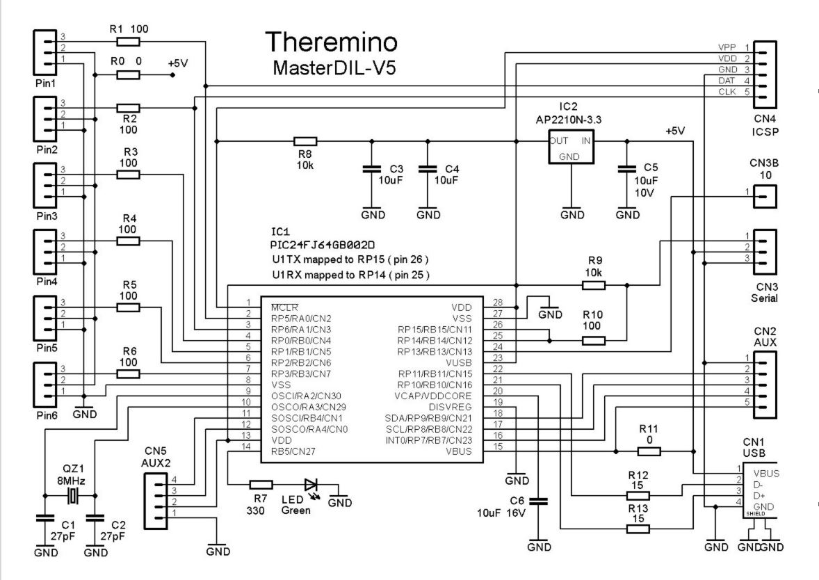
MasterDIL-V4 ModuleThe "Master" is the main module of the system Theremino. It puts in communication the software with the outside world via the USB.
The Master module has to be connected to a USB port (usb1, usb2 or usb3), and provides twelve Generic In-Out Pins. Earlier Master versions had 6 pins (versions 1 and 2), or 10 pins (Version 3).
So to know the Master version, just observe how many pins are listed.
The "USB" connector can connected one or two USB ports to draw a current of 500mA or 1000mA, or 900mA and 1800mA with the new usb3.
The "Serial Line" is a serial line to eventually connect slaves modules. Serial line has 3-poles (GND / +5 V / data). In the earlier versions, the fourth pole was used for the device "Master_ISO” to isolate the transmission line, but in the last Master versions it's used to provide access to Pin 7.
It is also possible to connect more than one Master with USB and serial transmission lines separated to increase the connection possibilities. It can, for example, use a high-speed serial line for devices that require a rapid refreshment and a second serial line, slower, for all the others.
Sensors and actuators are connected to the "IN OUT PINS" with standard cables (male-to-female extensions).
Connect the MasterJust connected to the USB, the master will automatically install its driver and, within a few seconds, the green LED starts to flash quickly. Each flash of the LED are 20 communication cycles, so the more you see it glowing nicely, the better.
Whenever possible, it is best to use more Master (possibly with a HUB) rather than one master and many Slaves. The pin of the Master can be configured with all possible types, while only some kinds of Slaves. Besides increasing the number of Master frequency trading it does not decrease, while the slow slave, in proportion to the number of pin to transmit. Finally, the serial line is more delicate than the USB and can produce errors of communication, in the presence of electrical noise.
If you use only the Master, do not connect Connection to USB. The serial line to the Slaves is always necessary.
Here you can see an LED connected to "Pin 1" and a standard extension connected to "Pin 6".
For a first project, prepare some LEDs.
The insulating tubes are used to distinguish the sides positive (red) and negative (black), but are not important. If you connect an LED on the contrary, it does not break and it is enough to turn it to make it work.
For further information on the preparation of these handy indicators, read here: www.theremino.com/hardware/outputs/actuators
Turn on Test LEDsSuppose we connect three LED indicators to Pin 1, 2 and 3.
Check that the positive of each LED (red) is connected to the "SIG" side and that the negative (black) is connected to the "GND" side.
Check that the Master is connected to a USB port and its green LED is flashing fast.
Start Theremino_HAL, that must immediately recognize the Master and list it as "Master 1".
If the Master has not been recognized, for example, because it is connected after opening the HAL, then you must press the button "Recognize".
The second line indicates that there is a "Slave 1" (not a real slave but a virtual slave that is inside the master) the following lines indicate that are six "Pins" available, named from "Pin 1" to "Pin 6".
To turn on the LEDs you must configure their "Pins" as DIG_OUT, Pwm_8 or Pwm_16.
With the DigOut type we could just turn on and off the LED, but with the Pwm types we can also adjust the brightness. The type Pwm16 communicates with 16-bit and is more accurate.
So, for this test, we will use Pwm_16, which uses some more bits in the serial line, but provides the best chance of control.
Select the row of "Pin 1" (that turns blue as you can see above), then press the left button of "Pin type" and choose "Pwm_16"
Set "Pin type = Pwm_16 " also for "Pin 2" and "Pin3".
At the end the list should look like the image on the right.
Now position the mouse pointer on one of the words "Sleep", press the left button, hold it down and move the mouse upwards.
The "Sleep" changes to a number from 0 to 1000, and the brightness of the LED of that line is adjusted from minimum to maximum. For better adjustment in the lower area, set "Logarithmic response" to all LEDs.
A little experiment is to set the "Slot 1" for the Pin 2 and 3, and try to adjust the brightness as before, you will see that all the LEDs, reading the same "slot" will change together.
Using external control programs (in the download folder you can find anything) or by creating them in .NET or Theremino Script, you can use these LEDs and any other sensor or actuator in many different ways.
The HAL Application CommandsFor more detailed instructions, read the documentation that you download with the HAL application.
- Auto reconnect: If enabled (orange color), it tries to reconnect the hardware if the communication is lost.
- Calibrate: Used only if there are connected "Slave" modules of type "CapSensorHQ".
- Configurations: Used to access the configuration file for manual editing.
- Recognize: Can serve if you connect the Master late or if you change the hardware configuration.
- Validate: Used if you change the hardware configuration. If you add or remove Master or Slaves, then the configuration is no longer valid and the "Validate" becomes active. If the configuration is not valid, the program HAL does not work. At this point you can choose to press "Validate" and to validate the new configuration, or to restore the original configuration by adding or removing the Master and Slaves as needed and press "Recognize."
- Error beep: If pressed, communication errors are highlighted with a sound.
- Lock Masters: If pressed, the HAL will connect only to the Masters having their names in the current list. In this way, you can keep (in separate folders) different HAL applications each linked to its specific hardware.
- Disconnect master: Removes the selected master from the list. In this way, we can eliminate the master side without having to physically disconnect them from the USB. After being eliminated, it is advisable to press "Block Master" so the next boot will be reloaded with the desired Masters only.
The most recent list of types are in the pages Technical-PinTypes and Hardware-Devices. For detailed instructions, read also the documentation that you download with the HAL application. To communicate with the hardware, you use the HAL (Hardware Abstraction Layer).
The "Theremino_HAL.exe" requires no installation and can be run in any folder on your system. The latest version of HAL can be downloaded from here: www.theremino.com/downloads/foundations. To communicate with the hardware, you need to keep active the HAL; you can minimize but do not close it.
Using the HAL alone, even without specific applications, you can check the hardware, try manual sensors and actuators and configure the properties of the In-Out pins.
Double-clicking on a line opens the graphics window that shows the trend of the signal on that line. With a single click on a first line and with one click on another, you can view them simultaneously.
All the numerical boxes are editable with the keyboard, with the mouse up/down, with the mouse wheel and the up and down arrows.
During the tests, it is very convenient to change the values in the column "Value" with the mouse (press left button on a number of the column "Value", hold the button and move the mouse up and down).
How to Use the SlotsEach line of the configuration corresponds to a hardware physical "Pin".
Each "Pin" corresponds to a sensor or actuator and is controlled with an appropriate "Pin type" and a "Slot":
- For the "Sensors" you configure the "Pin" as Input (Direction = get).
- For the "Actuators" you configure the "Pin" as Output (Direction = set).
The HAL program continuously repeats the following two steps:
- Reads hardware sensor and writes their values in the "Slot" assigned to each of them.
- Writes the value of each hardware actuator taken from the assigned "Slot".
The "slots" are in the "Memory Mapped File" called "Theremino1". This so-called "file" is not really a file, but a quick access memory area, shared by all the Theremino System applications.
Therefore one or many applications can, also simultaneously (Note 1), use the same slot to read the sensors, move motors or exchange data between them.
The HAL program serves only to communicate with the hardware via a master module and must remain lit, visible or minimized. However, if there are not hardware modules, the program HAL is not needed.
(Note 1) Slot communication must respect the following rules:
- One slot can be read by many applications and from the HAL, even simultaneously.
- Only a single application (or HAL) can write to a specific slot (otherwise they alternate randomly).
The twelve In-Out pins can be configured as:
- Not used
- Digital output
- PWM output
- Output for servo-controls
- FAST-PWM output with high resolutions for DAC (firmware V3.0 and up)
- STEPPER output to control the stepper motors (firmware V3.0 and up).
- Input to control STEPPER distance (firmware V3.0 and up).
- Digital input
- Input ADC for potentiometers and transducers
- Input for capacitive buttons
- Input for resistive transducers
- Count input, frequency and period
- Input for special transducers
Valid configurations
Not all the pins are configurable with every possible Pin Type.
The more recent list of Types are in the pages Technical-PinTypes and Hardware-Devices.
For detailed instructions, read also the documentation that you download with the HAL application.
Voltages and currents
The Input-Output pins work with analog signals from 0V to 3.3V. On the connectors is available the 5 Volt and a 3.3 Volt stabilized useful for some sensors. The maximum current for pins configured as output is +/- 15mA. For those that configured as input instead, should limit the voltage from -0.3 Volt to +3.6 Volt and not exceed these thresholds with currents greater than +/-100uA (see technical/pin-types and technical/tables-and-notes for more information on currents and voltages).
Connectors
From version 4 onwards, all the connectors have been replaced with the connectors for the standard female-female cables.
Connect the Slave ModulesThe cables to connect the serial line that goes to the Slaves are the same used to connect sensors and actuators to the Input / Output Pins.
But you should not confuse the two lines, wiring errors not cause damage, but if you do not make the right connections, these will not work.
Even if the connectors are the same, be careful! The "Pin" connectors are used for sensors and actuators while the "Serial" connectors are used to connect "Master" and "Slave" modules one to each other.
The serial line from the Master must be connected to the "IN" of the first "Slave".
To add a second slave, the "OUT" connector of the first slave is used, and so on up to 200 slaves.
The slaves can be connected in any order but if you change their disposition or their number the hardware configuration will be misaligned from the HAL program.
Therefore, after connecting the Master and Slave chain, you press the button "Recognize" and then eventually "Validate", to accept the new hardware configuration to Theremino_HAL.
Apply an External Power SupplyTo power motors and actuators with strong currents, the simplest and safer solution is to use a USB HUB connected to a 5 Volt and some Ampere power supply.
Otherwise it is possible to discontinue the serial line to the slave modules, with an adapter and an external power supply. www.theremino.com/hardware/outputs/actuators
For applications without slave modules, or to provide more current (to the six master Pins only), you can make this change:
Unsolder (or break with the clippers) the resistor R0 and solder red and black wires to bring the +5 Volt from an external power supply.
We recommend to avoid the use of additional power supplies as much as possible.
When designing a system that is also connected to a wall outlet, you should pay attention to:
- Place correctly the GND wires (star connections)
- Do not let the noise coming from the power supply cross the delicate connections and produce errors.
- Avoid strong current pulses caused by lightnings that may damage the components.
- Avoid construction errors or faults that can damage components or cause hazards to users.
Precautions to be taken: The Theremino System is a "Freeware", "Open Source" and "Not for Profit" project and its components are "mounting kits" and not "finished products". Therefore, when connecting the modules in a system, you must respect the limits of the law, radio frequency emissions and obtain the necessary certifications. In order to reduce noise to the law limits, which might be necessary depending on the case, use shielded cables and metal containers or other techniques. Manufacturers and retailers of the system Theremino are not aware of the actual conditions of use of the modules and, therefore, can not respond to improper, illegal or dangerous use of them.
Provide High Current Without External Power SupplyMotors, actuators and servos can have a current "surge" of more than the 500 mA (or 1000 or 1800) supplied by USB, but the average current is much lower. This means that it is able to drive four servos at the same time, but just one of them at full speed for a moment can stop the USB communication. Depending on the model of the servo and of their power this problem may be more or less serious.
Some PCs and notebooks do not suffer from this problem. If you exceed the current, they lower the 5 Volt and restore as soon as the current falls. The actuator slows down a bit, it takes more time to get into position and then everything goes happily.
Other manufacturers have included a sadistic "warning" circuit that, as well as warn, blocks all the USB connection. These machines are very picky; they also prevent very short duration current bursts, thus preventing solving the problem with a large electrolytic which can satisfy the surge current of the engines. If you add, for example, a 4700 uF capacitor, the USB port does not light up, that is, turns on, fails to charge the capacitor, exceeds the current, turns off immediately and stops, waiting for a human to press OK.
So whoever encounters these problems should try first of all to connect a 2200 or 4700 uF capacitor between GND and +5 Volt and try to move all the engines repeatedly, trying to get it to use as much current as possible.
If with the capacitor everything falls into place, you stop here, otherwise you can add, in addition to the large capacitor, a "current limiter".
Limit the currentA current limiter, followed by a large electrolytic capacitor, can solve even the most difficult situations, without having to add an external power supply. The limitation is precise, much better than that of PTC normally used for the USB, and in case of short circuit, the output "shuts down" and "restores" automatically as soon as you remove the short ("foldback" operation).
Changing the values of the resistors you can choose the maximum current.
The limiter must be interposed between the +5 Volt coming from the USB and the power track that goes to the pins. This can be done on both the Master and Slaves by cutting the trail that leads from the +5 Volt to the pins and soldering three wires.
Note: Only the pins power should be limited - not the processors power supply. You do not have to interpose limiters along the serial line.
Full Eagle projects, 3D images and LTSpice simulations for this limiter and for a smaller version, can be downloaded from here: www.theremino.com/hardware/outputs/actuators.
Connect the Capacitive ButtonsIt would be good to procure a certain number of standard extensions with connected wires that can be cut in order to obtain females and males at a price so low that it is not worth making them.
Some pieces of thread, alone or with squares of copper or aluminum tape attached, can act as capacitive keyboard.
For more details see the attached pdf.


Comments