


Hardware components | ||||||
| × | 1 | ||||
| × | 1 | ||||
 |
| × | 5 | |||
 |
| × | 2 | |||
 |
| × | 1 | |||
 |
| × | 2 | |||
 |
| × | 1 | |||
 |
| × | 1 | |||
 |
| × | 1 | |||
 |
| × | 3 | |||
 |
| × | 1 | |||
This unique probe is modelled after one stage of the legacy 1971 TTL tester by Hewlett Packard known as the HP 10529A. (For context, please refer to the manual at HP 10529A Operation Only.pdf (linked from xdevs.com) ). Modified for just two inputs instead of the 10529's barrage test of 16 inputs. This older probe was intended to be powered from the known good (TTL) board, and compare identical logic on a UUT ("unit under test") board target to a reference IC board, running identical parallel input conditions.
Inspiration: amateurs that repair or refurbish older coin-operated Video Game terminal on repair chat groups. Used 10529A Test (50+ year old) Kits bid over $1000 on ebay! Someone recently contacted me and I supplied some common TTL ICs for his 10529's reference card library. That is how my idea started....
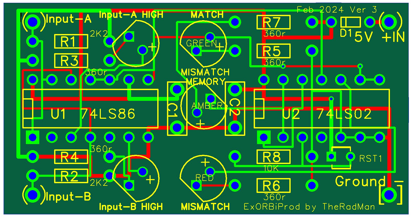
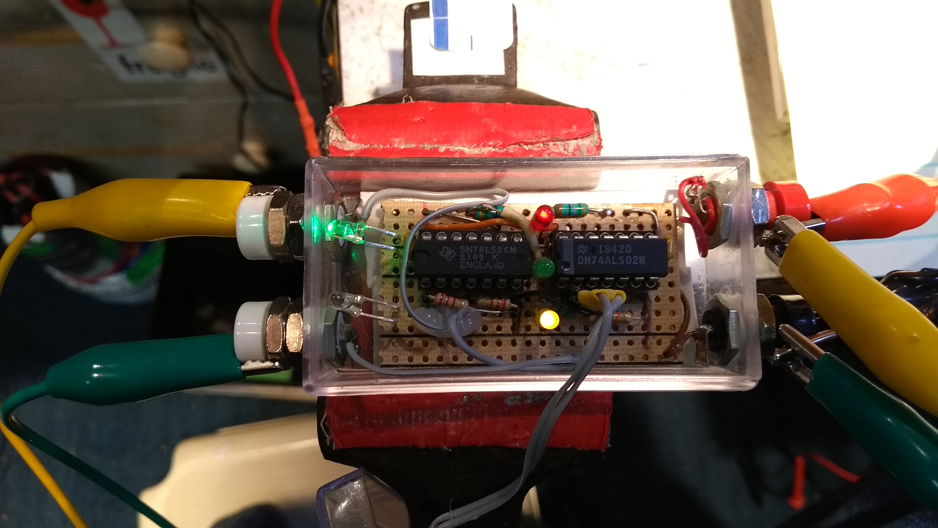
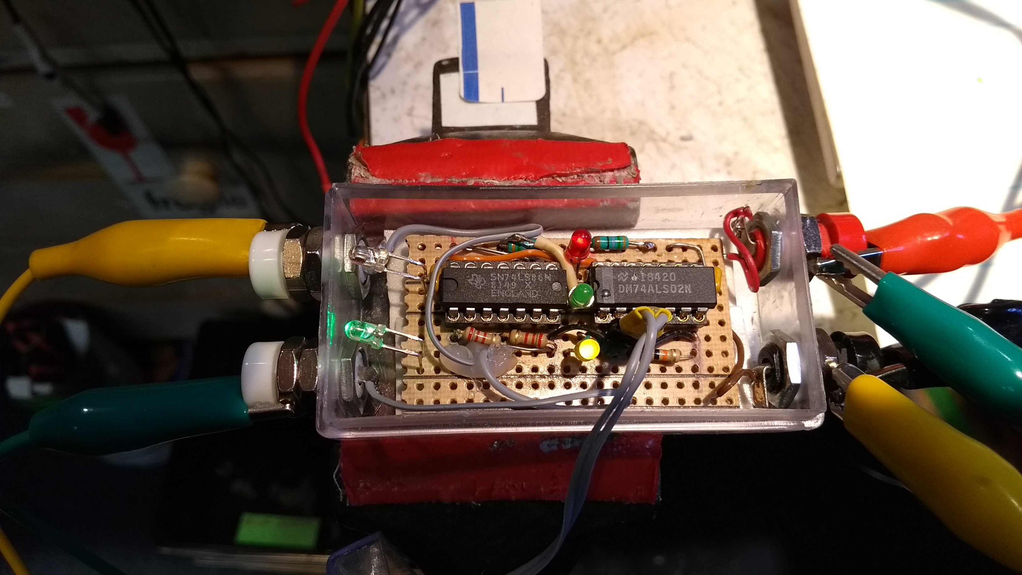
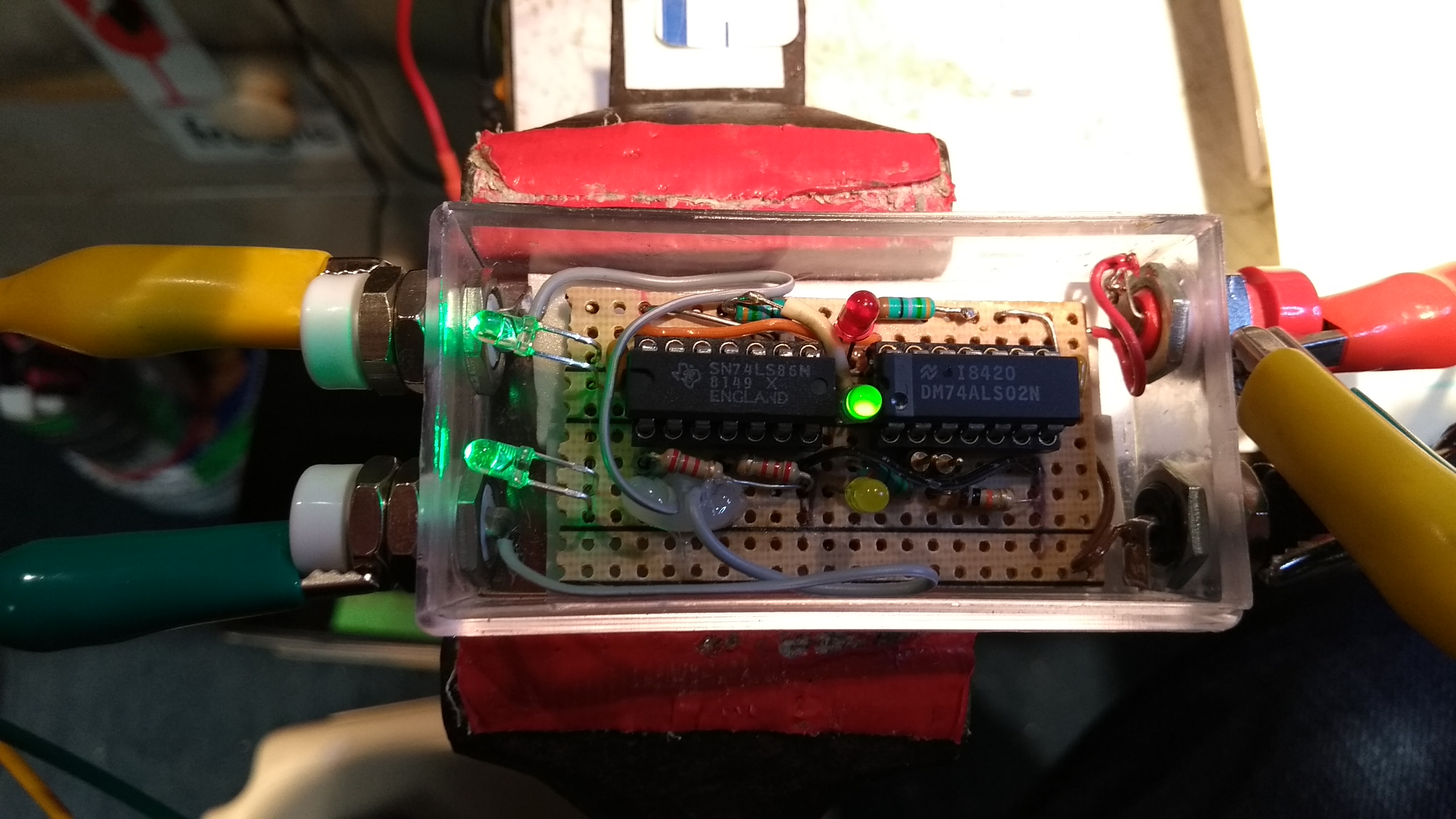
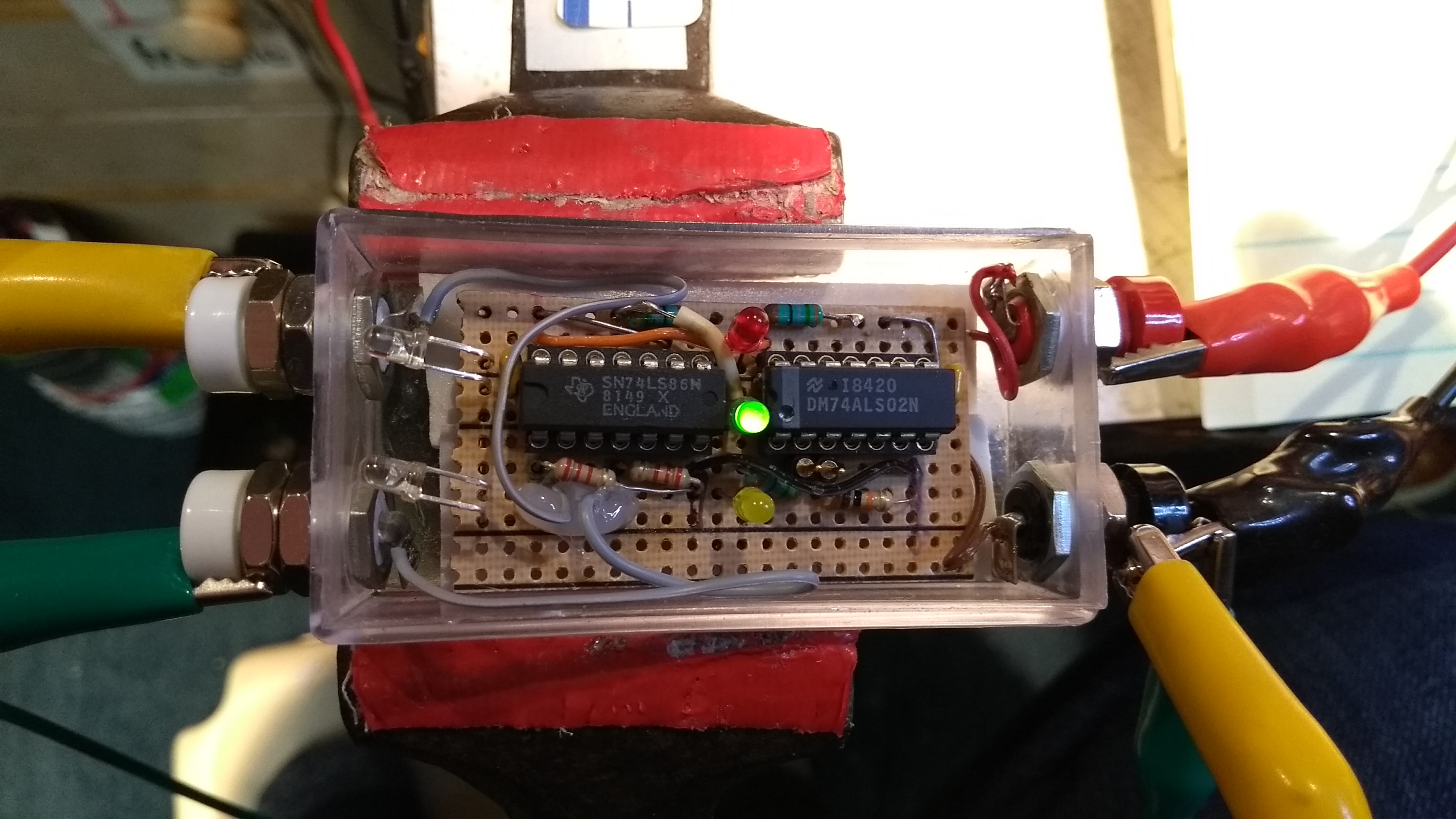
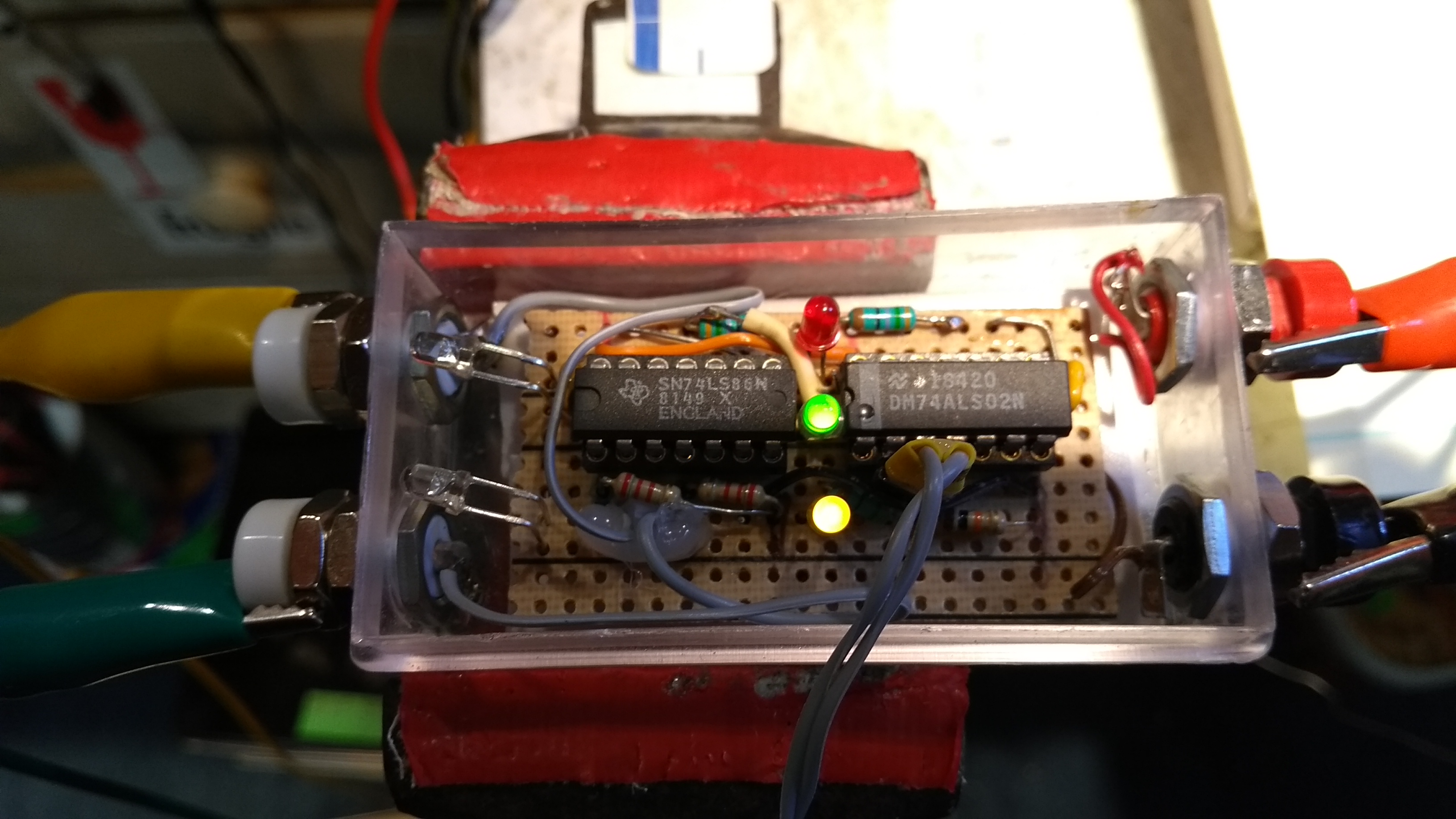
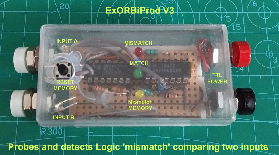
Prototype: Built in small case with four 'banana post' jacks; two white TTL LOGIC inputs on one side and two Red & Black 5V power jacks on the other side. One momentary switch resets a 'Trap' LED, one of five indicators. Simply described as a XOR Quad and OR Quad ICs combined as a dual input Logic comparison probe. Unique in that the device combines two Logic probes in one.
Name: ExORBiProd for Exclusive OR Bi-Input Prod (Verb: as in an act of probing)
Versions:
- V1 discrete transistor good for LV_ logic to 3V3. I built that out of 10 2N3904 NPN small signal BJT's (I will include a schema jpeg once I scan a napkin)
- V2 CMOS version, similar schematic to this TTL based design using 4070 and 4001 (also on a napkin right now)[update- 4xxx sure is slow but I like that I can potentially use this V2 probe for Automotive 13.8V Circuits]
- V3 TTL ; this design and post, using 74_86 and 74_02, in TTL family LS in PDIP-14 (socketed, so when my ALS arrive, I can test for ALS speeds)
- V4 (proprietary, commercial, using Atmel)
- planned: ECL (proprietary)
Tested to 20 MHz in (A)LS, somewhat glitchy in CMOS family's
(anticipated) Issues: input Z on 74_86, donor current draw, Test speed(glitching)
Inspiration: HP 10529A Test Probe : UUT 16pin DIP-clip is compared to reference card that contains a known good TTL Logic IC....and requests from forums involved in legacy TTL [blind]repair
10529A Reference: refer to the 1970 document found at this link 10529-90005_10529A_Logic_Comparator_Operating_and_Service_Manual_197308.pdf (bitsavers.org) with schematic on pages: 57 & 58. Direct your attention to page 58, the stage with U1D, U2D, CR1, R10, R11, C2, and LED DS1. Section 4-16 on Page 16 and figure 4-2 on page 17 (of the PDF) to help in understanding one of 16 stages.
Instead of the monostable pulse stretching behavior of the channel indication, I chose to indicate mismatch directly and then provide a TRAP LED adopted from 4 decades of Telecommunications experience with TRAP LED stages that signal CRITICAL, MAJOR and MINOR Alarm indicators and the TRAP SR Latch stage LEDs. Early equipment from the 1980's utilized crossed OR gates and provided one momentary that reset the Latch. The MEMORY LED intends to indicate fast events and it has been good at finding delayed phase as well.
I tend to design my Electronics bench toys by grabbing bits and parts of other toys and McGiver'ing (sorry to Richard Dean Anderson) a solution that I need.
This tool helps me probe and compare known and unknown side-by-side boards with a 3M DIP-clip (3M-923700) and Test-Hook-Clip jumpers, then mark the issues found, to check on the Oscilloscope.
Cost: Maybe $14 Cdn with time and energy on perfboard and STL 3D case


Comments