

Hardware components | ||||||
| × | 1 | ||||
| × | 1 | ||||
| × | 1 | ||||
| × | 1 | ||||
| × | 1 | ||||
| × | 1 | ||||
| × | 16 | ||||
| × | 1 | ||||
| × | 1 | ||||
| × | 1 | ||||
| × | 1 | ||||
| × | 2 | ||||
| × | 1 | ||||
| × | 1 | ||||
| × | 1 | ||||
| × | 1 | ||||
| × | 1 | ||||
| × | 1 | ||||
| × | 1 | ||||
| × | 1 | ||||
| × | 1 | ||||
| × | 2 | ||||
| × | 1 | ||||
| × | 1 | ||||
| × | 1 | ||||
| × | 1 | ||||
| × | 1 | ||||
| × | 10 | ||||
| × | 12 | ||||
| × | 20 | ||||
| × | 4 | ||||
| × | 4 | ||||
Software apps and online services | ||||||
 |
| |||||
A project that uses a 3d printed rack-and-pinion, blower fan, an Arduino Due, and a laser-cut base plate in a slide whistle assembly. Project is functional, and mostly-complete, but can use a little bit of tidying-up, It may eventually incorporate limit switch to define a home position (currently requires manual homing).
DetailsHow this project came to be:
Build video:
This project was really fun, and kind of evolved in a very rambling sort of way. It started off in a completely different direction - the plan was to get a reed-based instrument working. At some point, I actually got a saxophone reed to work with a 3d-printed mouthpiece... just barely! And with a 5 foot piece of PVC, it made for a pretty interesting almost-didgeridoo-like sound. After some tweaking, I finally got a fipple to do that, too (in the build video).
Getting a fully functional PVC reed instrument is still a goal of mine, but for the time being, I decided to try out 3d printing a fipple and making a fipple flute. The first working iteration of that fipple is featured in the Cream Cover I did last month:
https://www.youtube.com/watch?v=VaGBY9zagCU
Long story short, this ended up becoming a slide whistle to change notes. It became apparent that I could re-use some code I had from the last project I did back in May-June 2020 (A "Semi Manual Electric Rail Kalimba" aka the SMERK), and that was a huge plus.
So enough of my rambling - here's the design:
Design Overview
Design philosophy is to use relatively cheap/easy-to-acquire parts like those used for 3d-printers (centrifugal blower fan, 8mm linear rail), and 3d-printed + laser cut components.
Hardware/mechanical design was all done in Fusion360. Some things that required optimization and iteration were:
- the fipple (part of the whistle that air is forced through). I made a blown up and cross-sectioned version for explanation in the upcoming build video(s)
- the height and size of the pinion gear/motor mount subassembly (too large a gear = too much torque for motor)
- the fit of the O-Ring/8mm-rail Assembly (there's a tiny 3d-printed part there that holds the o-ring, whose diameter took some time to optimize, and it's still a bit too tight)
The design uses a lot of M3 heated inserts and 1/4-20 screws/tapped holes... mostly because I have tons of these. [Achievement Unlocked: Imperial and Metric in Same Design.]
Firmware and Electrical Hardware:
The microcontroller board used is the Arduino Due with a CNC Shield v.3 w/ A4988 drivers. This combination is a favorite of mine for getting MIDI + USB + NEMA17 Stepper Motors going quickly.
The stepper motor is a 2A NEMA17 from STEPPERONLINE.
The microstepping configuration is set up to 1/8th microstepping. This provides a decent balance of speed and quiet.
The firmware is sort of a rough/ongoing sketch for the Arduino Due. I see this as sort of a quick, but generic "correlate some subset of MIDI to a stepper motor position". It uses some dead-waits that I'll eventually design out, but for now it seems to do the job.
Warning: some variables are named for a similar project I have going (Semi-Manual Electric Rail Kalimba, so apologies for the "kalimba" and "flute" inconsistencies). The firmware is configured to use the Y-Axis of the CNC shield as I've got some ongoing work on the X-Axis for controlling another instrument simultaneously (will post that project soon, I hope). The code here relies on the Arduino MIDIUSB Library, which is a very simple way to get a class-compliant MIDI USB device working through the Due's Native USB port.
A pre-processor Macro "#define" for isTuning exists. This enables the user to tune the instrument. Connect via the programming USB port and type a number of steps. Use those numbers to populate the "pulleyPositions.h" definitions.
Fabrication
- The base-plate is laser cut (.dxf's) on 1/4" clear plastic
- Most other components are 3d-printed
- 1/2" ID PVC Pipe is cut to appx 400mm in length
Some notes on this project:
This project requires laser cutting, installing heated inserts w/ a soldering iron, 3d printing and some tuning in...
Build instructionsStep 1
It's recommended to watch the video to get a general feel for design principles and some of what's involved in the assembly, and it would be good to carefully read through instructions before attempting!
Step 2
At this point, it's time to procure components for the build and to start fabricating. Bill of materials is listed in Components Section of this page along with some links to parts I used.
For the 3d-printed parts, I've used an FDM 3d printer (Creality CR-10): .stl files included, and for the base plate + connector piece, I used a laser cutter: .dxf files included.
In order for full thread engagement + not having screws poke through the bottom, I recomment 1/4" or thicker Acrylic for the laser cut pieces.
For those using a print bed that's less than 300mm x 300mm --> I recommend printing the "shorter" of the two racks. Another option (if you want the longer one) would be to design and cut a laser-cuttable rack, maybe with some sort of a 3d-printed adapter for mating to the 8mm rod.
Step 3
Note: some of these heated insert spots were never actually used in the final version, so I've tried to indicate where they aren't needed
Using a soldering iron (either with a "normal sized' tip or with a heated insert-specific tip), install the heated inserts. If it's your first time doing this, I recommend printing a few test pieces and trying this process out before doing it on a part you care about!
Components w/ Heated Inserts
- Motor Mount/Base Plate Bracket
Whistle Top/Fipple:
Pinion Gear:
Stability Bracket:
Pipe and Bearing Clamp Bracket:
Pipe Bottom Clamp Bracket:
Step 4
Now that we've got some beautiful, laser-cut acrylic plates, let's take a drill to them! to tap these 1/4-20 holes, I like to use a hand-drill: I get good enough threads and tend not to need cutting fluid on acrylic.
Step 5
At this point, it's time to use the 1/4-20 x 5/8" screws to attach the 3d printed brackets to the build plate.
Step 6
(Note: if using LM8UU, make sure to put that onto the rod before this step).
On one end, attach plunger adapter to rod. Now do the same on the other end with the 3d printed rack piece.
Secure in place with epoxy.
Once the epoxy has dried, attach O Ring to plunger piece (should fit in the little "groove" designed for it)
Step 7
At this point, insert the plunger into the PVC Pipe, place the pipe on the clamp brackets, and attach M3x16 screws through the top bracket pieces to clamp down on the pipe.
Step 8
Attach Blower Adapter to Whistle Top components using M3x16 screws:
Then attach Blower Fan using M3x22mm screws and M3 Hex Nuts. Attach loosely, and then slide the fan into place:
Press Assembly onto the end of the PVC Pipe:
Step 9
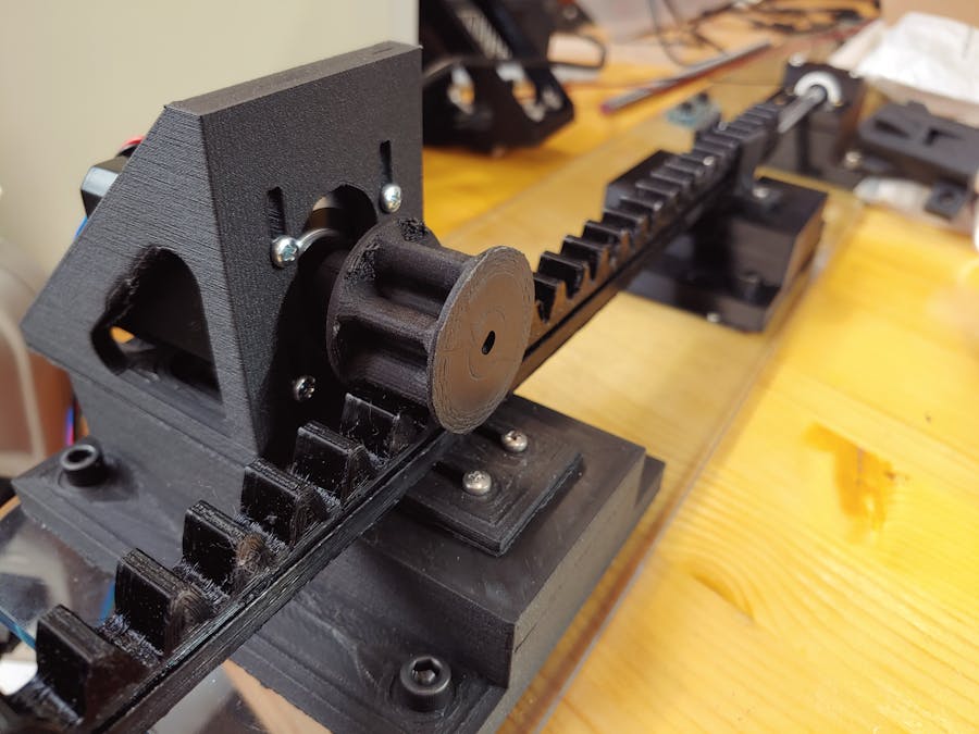
Now it's time to get the drive mechanism together. This requires a motor mount, the motor, and the pinion gear to mate with the rack.
I ended up biasing the motor mount slots to be all the way "back" away from the rack piece before attaching. Unfortunately, the motor makes it difficult to adjust this after-the-fact (needs a re-design), so you pretty much have to pick a position in the slot and stick with it. As mentioned, I would start with it "all the way back". There are 2x M3 screws that hold it together in the front, and 4x 1/4-20 x 1" screws in the back (with hex nuts underneath).
Once the motor mount is attached, attach the motor to it using M3x10 screws. Keep them loose until you've attached the pinion gear and aligned it into the slot.
Attach the pinion gear using a set screw. You can leave it a little loose while you're adjusting all the slots here, but once done, make sure it's tight and can spin the motor freely without slipping.
It's a little tricky to fit this on the rack, but with some rotating the pinion and moving the rack, you should be able to get the two to mate. Make sure the motor slots are loose when you do this so you can "lift" the motor/pinion as needed.
Then, bias the motor slots down until you're making good contact between the rack and pinion. That height can be adjusted later if things are binding or are too loose, but "mostly down" is where I ended up.
Step 10
I use the CNC Shield because it makes it really easy to add additional stepper motors and drivers to a project (or let me control more instruments at one time).
Important: For the Arduino Sketch here, it works on the "Y" axis of the CNC Shield and with 1/8 microstepping. So populate the first two jumper positions (M0 and M1) on the shield. And attach the motor. In the StepperOnline motor I used, see image below for polarity. If you get it wrong, you can always flip the connector over (or else change the tuning positions to be negative in code!).
See here for more info about this component: http://www.zyltech.com/arduino-cnc-shield-instructions/
Power up the Fan and the Motor Driver with 24V Power Supplies (or 12V if you go with a 12V fan option).
Note: you can (and should) tune the current for the driver depending on what motor you end up using.
FilesArduino_Due_Sketch_Rev3.zip: Arduino Due Sketch and Header FIles
Whistle_Rack_and_Pinion_build_files.zip: STL's, DXF's, STEP File for build
Images.zip: Build and Design Image Files
Demo_Slide_Whistle.mp4: Demo of Slide Whistle in Action


Comments