


You can access the source code files via this link.
This project aims to investigate how external triggers enhance STM32 ADC functionality. By exploring how ADC conversions can be synchronized with external events, we seek to understand their impact on analog data acquisition. Through simple experiments, we'll uncover how external triggers optimize efficiency, flexibility, and real-time processing in STM32 microcontrollers.
In real-world applications, external triggers play a crucial role in embedded development. They offer synchronized data acquisition with external events, enhancing system efficiency, flexibility in operation, and facilitating real-time response to dynamic input signals. From industrial automation to IoT devices, the utility of external triggers extends across various industries, ensuring precise monitoring, control, and data acquisition.
To begin this project, we'll configure the ADC to read the analog voltage from the potentiometer. Then, we'll enable regular conversion mode and set the external trigger source to EXTI Line11. Next, we'll activate UART communication to interface the ADC value and external trigger status. Final ly, we'll simulate the circuit design using Proteus software.
Step One:- Open CubeMX & Create New Project Choose The Target MCU STM32F103C6 & Double-Click Its Name
- Go To The Clock Configuration & Set The System Clock To 8MHz
Configuration for the GPIO Mode:
- Configure GPIO Pins PA2 and PA3 as Output Pins, with one indicating the loop status and the other for callback notifications.
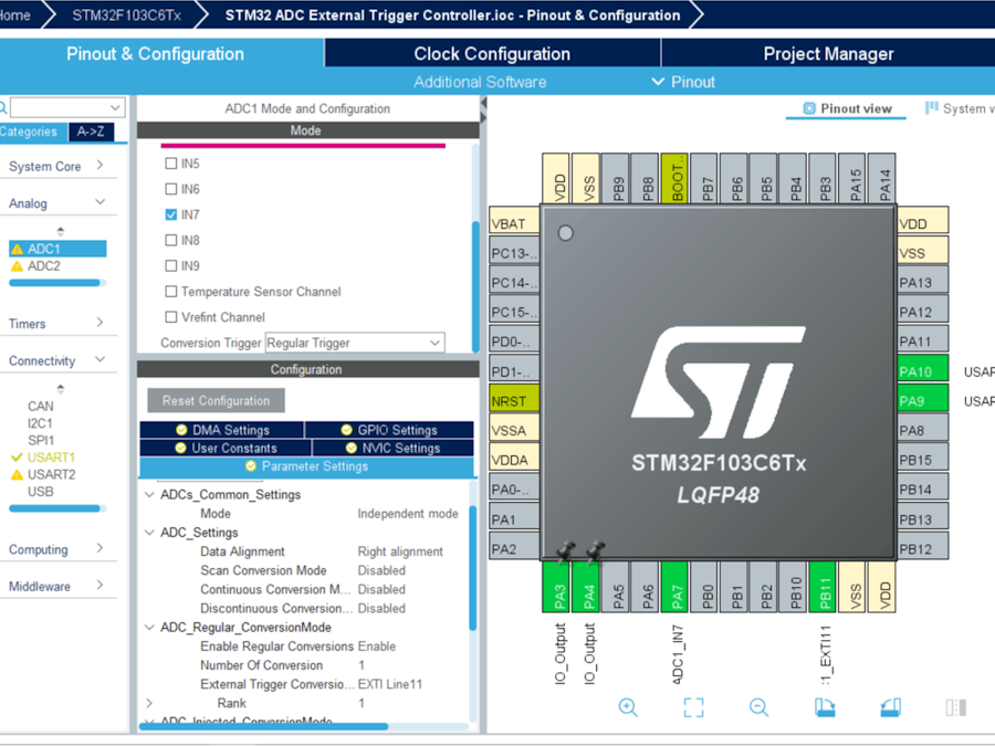
Configuration for the ADC Mode:
- In the Categories tab, select the [ADC1, enable IN7]
- In the Parameter settings tab, Enabler Regular Conversion Mode
- In the NVIC settings tab, Enable ADC1 and ADC2 global Interrupts and [EXTI ligne [15:10] interrupts
Configuration for the UART Mode:
- Enable USART1 Module (Asynchronous Mode)
- Set the USART1 communication parameters (baud rate = 115200, parity=NON, stop bits =1, and word length =8bits)
- Generate The Initialization Code & Open The Project In CubeIDE
- Write The Application Layer Code
- Open Proteus & Create New Project and click next
- Click on Pick Device
- Search for STM32F103C6 & POT & BUTTON & LED-GREEN & LED-REED
- Click on Virtual Instruments Mode then choose VIRTUAL TERMINAL
- Click on Terminal Mode then choose (DEFAULT & POWER &GROUND)
- finally make the circuit below and start the simulation
If you have any questions or suggestions don't hesitate to leave a comment below


Comments