


Hardware components | ||||||
 |
| × | 1 | |||
| × | 1 | ||||
 |
| × | 1 | |||
| × | 1 | ||||
| × | 1 | ||||
| × | 1 | ||||
 |
| × | 1 | |||
 |
| × | 1 | |||
Software apps and online services | ||||||
 |
| |||||
 |
| |||||
 |
| |||||
_4YUDWziWQ8.png?auto=compress%2Cformat&w=48&h=48&fit=fill&bg=ffffff) |
| |||||
Hand tools and fabrication machines | ||||||
 |
| |||||
 |
| |||||
Our project is divided into 2 major parts:
1. Drone
2. AI model
Block Diagram
The Drone moves in the forest and captures the various data. Based on the trained data, it analyses the current situation and provides results.
There are variety of data can be analysed such as Image (forest biodiversity), temperature of forest, CO2 level, humidity, location. The drone's job is to fly around the forest and capture various data.
In our project, our main goal is to monitor the illegal deforestation and forest coverage using edge AI techniques. To capture the data, we are using camera on drone to capture the images of forest from sky. For remote control, we are using Wi-Fi network (prototype level).
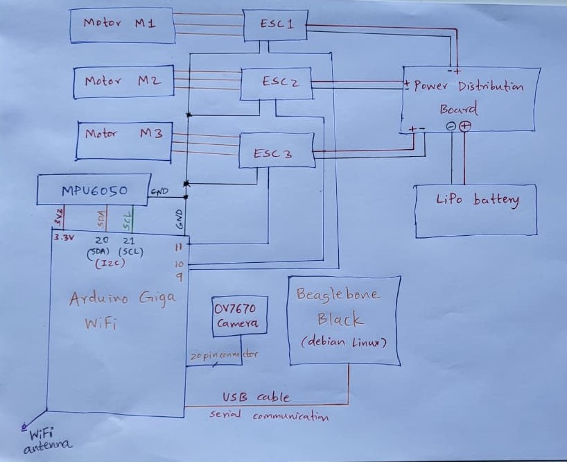
Drone Parts:
Following are the detailed parts of our Bioscope Drone:
1. Drone Frame: Physical frame of the drone for placing various components. We have designed our own drone frame.
2. BLDC motors: DJI 2212/920 KV motors.
3. Battery: LiPo battery 3S1P 11.1V 2700mAh to power the drone.
3. Power Distribution board: Generic power distribution board to distribute the
4. Electronic Speed Controller: ESC 10A speed controller for controlling motor speed.
5. IMU unit: MPU6050 6-axis motion sensor (3-axis accelerometer + 3-axis gyroscope). It measures acceleration (X, Y, Z) and angular velocity (pitch, roll, yaw). This is useful for PID controller for stabilizing the drone and moving from one part to another.
6 OV7670 Camera module: It captures the raw frame of image.
Here is the example of image captured by OV7670 camera.
7. Arduino Giga Wi-Fi: It serves as main flight controller, wireless controller and image capturing hardware.
Main Flight Controller
Responsible for reading sensor data from the MPU6050 (gyroscope + accelerometer) and other peripherals, processing flight algorithms, and sending control signals to the ESCs and motors. It maintains stability, orientation, and executes commands received from the wireless controller.
Wireless Controller
The wireless controller serves as the user interface for piloting the drone, enabling real-time communication between the pilot and the flight controller. It transmits commands such as throttle, pitch, roll, and yaw, allowing smooth navigation and responsive control of the drone in flight. For our project, we have made Wi-Fi webserver for controlling the drone motors. here is the demo of such wireless control.
Here is the wireless drone motor control Arduino code
/*
#bioscope
#EDGE AI hackathon

wireless drone motor control Arduino code
author: Ninad Waingankar

*/
#include <WiFi.h>
#include <Servo.h>
#include "arduino_secrets.h"
//most probably server IP: http://10.182.232.135
//make sure you connect your phone/laptop to the same wifi network to which GIGA is connected
// WiFi credentials (stored in arduino_secrets.h)
char ssid[] = SECRET_SSID;
char pass[] = SECRET_PASS;
int status = WL_IDLE_STATUS;
WiFiServer server(80);
Servo esc;  // ESC control
void setup() {
Serial.begin(9600);
esc.attach(9);  // ESC signal wire on pin D9
// Arm ESC at minimum throttle
esc.writeMicroseconds(1000);
delay(3000);  // wait 3s for ESC to initialize
// check for the WiFi module:
if (WiFi.status() == WL_NO_MODULE) {
Serial.println("Communication with WiFi module failed!");
while (true);
}
// attempt to connect to WiFi network:
while (status != WL_CONNECTED) {
Serial.print("Attempting to connect to Network named: ");
Serial.println(ssid);
status = WiFi.begin(ssid, pass);
delay(3000);
}
server.begin();
printWifiStatus();
}
void loop() {
WiFiClient client = server.accept();   // listen for incoming clients
if (client) {
Serial.println("new client");
String currentLine = "";
while (client.connected()) {
if (client.available()) {
char c = client.read();
Serial.write(c);
if (c == '\n') {
if (currentLine.length() == 0) {
// send HTTP headers
client.println("HTTP/1.1 200 OK");
client.println("Content-type:text/html");
client.println();
// Webpage content
client.print("Click <a href=\"/H\">here</a> to start motor<br>");
client.print("Click <a href=\"/L\">here</a> to stop motor<br>");
client.println();
break;
} else {
currentLine = "";
}
} else if (c != '\r') {
currentLine += c;
}
// Check requests
if (currentLine.endsWith("GET /H")) {
esc.writeMicroseconds(1200);   // run motor at slow speed
Serial.println("Motor ON");
}
if (currentLine.endsWith("GET /L")) {
esc.writeMicroseconds(1000);   // stop motor
Serial.println("Motor OFF");
}
}
}
client.stop();
Serial.println("client disconnected");
}
}
void printWifiStatus() {
Serial.print("SSID: ");
Serial.println(WiFi.SSID());
IPAddress ip = WiFi.localIP();
Serial.print("IP Address: ");
Serial.println(ip);
long rssi = WiFi.RSSI();
Serial.print("signal strength (RSSI):");
Serial.print(rssi);
Serial.println(" dBm");
Serial.print("To see this page in action, open a browser to http://");
Serial.println(ip);
}
You must have your Wi-Fi credentials stored in header file such as:
//arduino_secrets.h
#define SECRET_SSID "Nin"         //your wifi name
#define SECRET_PASS "Ian*Wa@59"    //your wifi password
Here is the image of Wi-Fi webserver on phone:
Here is the drone motor control wirelessly:
Image Capturing Hardware
The captured raw image data from OV7670 camera module is directly transferred to Arduino Giga which has onboard 20 pin connector for camera module along with image capturing support which makes it easier for use.
Here is the code for realtime image capture of OV7670 using Arduino Giga (based on webserial camera code example) on Arduino GIGA:
/*
Bioscope
For EDGE AI Hackster competition
* This example shows how to capture images from the camera and send them over Web Serial.
camera: OV7670
* Initial author: Sebastian Romero @sebromero
* modified author: Ninad Waingankar
web image server: https://arduino.github.io/labs-pages/web-serial-camera/
*/
#include "camera.h"
#ifdef ARDUINO_NICLA_VISION
#include "gc2145.h"
GC2145 galaxyCore;
Camera cam(galaxyCore);
#define IMAGE_MODE CAMERA_RGB565
#elif defined(ARDUINO_PORTENTA_H7_M7)
// uncomment the correct camera in use
#include "hm0360.h"
HM0360 himax;
// #include "himax.h";
// HM01B0 himax;
Camera cam(himax);
#define IMAGE_MODE CAMERA_GRAYSCALE
#elif defined(ARDUINO_GIGA)
#include "ov767x.h"
// uncomment the correct camera in use
OV7670 ov767x;
// OV7675 ov767x;
Camera cam(ov767x);
#define IMAGE_MODE CAMERA_RGB565
#else
#error "This board is unsupported."
#endif
/*
Other buffer instantiation options:
FrameBuffer fb(0x30000000);
FrameBuffer fb(320,240,2);
If resolution higher than 320x240 is required, please use external RAM via
#include "SDRAM.h"
FrameBuffer fb(SDRAM_START_ADDRESS);
...
// and adding in setup()
SDRAM.begin();
*/
constexpr uint16_t CHUNK_SIZE = 512;  // Size of chunks in bytes
constexpr uint8_t RESOLUTION  = CAMERA_R320x240; // CAMERA_R160x120
constexpr uint8_t CONFIG_SEND_REQUEST = 2;
constexpr uint8_t IMAGE_SEND_REQUEST = 1;
uint8_t START_SEQUENCE[4] = { 0xfa, 0xce, 0xfe, 0xed };
uint8_t STOP_SEQUENCE[4] = { 0xda, 0xbb, 0xad, 0x00 };
FrameBuffer fb;
/**
* Blinks the LED a specified number of times.
* @param ledPin The pin number of the LED.
* @param count The number of times to blink the LED. Default is 0xFFFFFFFF.
*/
void blinkLED(int ledPin, uint32_t count = 0xFFFFFFFF) {
while (count--) {
digitalWrite(ledPin, LOW);  // turn the LED on (HIGH is the voltage level)
delay(50);                       // wait for a second
digitalWrite(ledPin, HIGH); // turn the LED off by making the voltage LOW
delay(50);                       // wait for a second
}
}
void setup() {
pinMode(LED_BUILTIN, OUTPUT);
pinMode(LEDR, OUTPUT);
digitalWrite(LED_BUILTIN, HIGH);
digitalWrite(LEDR, HIGH);
// Init the cam QVGA, 30FPS
if (!cam.begin(RESOLUTION, IMAGE_MODE, 30)) {
blinkLED(LEDR);
}
blinkLED(LED_BUILTIN, 5);
}
/**
* Sends a chunk of data over a serial connection.
*
* @param buffer The buffer containing the data to be sent.
* @param bufferSize The size of the buffer.
*/
void sendChunk(uint8_t* buffer, size_t bufferSize){
Serial.write(buffer, bufferSize);
Serial.flush();
delay(1); // Optional: Add a small delay to allow the receiver to process the chunk
}
/**
* Sends a frame of camera image data over a serial connection.
*/
void sendFrame(){
// Grab frame and write to serial
if (cam.grabFrame(fb, 3000) == 0) {
byte* buffer = fb.getBuffer();
size_t bufferSize = cam.frameSize();
digitalWrite(LED_BUILTIN, LOW);
sendChunk(START_SEQUENCE, sizeof(START_SEQUENCE));
// Split buffer into chunks
for(size_t i = 0; i < bufferSize; i += CHUNK_SIZE) {
size_t chunkSize = min(bufferSize - i, CHUNK_SIZE);
sendChunk(buffer + i, chunkSize);
}
sendChunk(STOP_SEQUENCE, sizeof(STOP_SEQUENCE));
digitalWrite(LED_BUILTIN, HIGH);
} else {
blinkLED(20);
}
}
/**
* Sends the camera configuration over a serial connection.
* This is used to configure the web app to display the image correctly.
*/
void sendCameraConfig(){
Serial.write(IMAGE_MODE);
Serial.write(RESOLUTION);
Serial.flush();
delay(1);
}
void loop() {
if(!Serial) {
Serial.begin(115200);
while(!Serial);
}
if(!Serial.available()) return;
byte request = Serial.read();
switch(request){
case IMAGE_SEND_REQUEST:
sendFrame();
break;
case CONFIG_SEND_REQUEST:
sendCameraConfig();
break;
}
}
Here is the live demo:
Drone Circuit DiagramWe have designed the drone frame with 2 different models.
1. Quadcopter frame (if you are using 4 motors)
This is the quadcopter frame designed on autodesk for 4 motors. Please look for.step file attached below.
This step file can be used for 3D printing.
Live 3D printing of plastic parts for example:
2. Tricopter frame (3 motors)
We have used this tricopter frame in our Bioscope drone.
This design was generated using following Python code.
#Python file to generate .dxf file for modelling and Laser cutting of tricopter frame

#BioScope: Edge AI Drone for Forest Biodiversity
# For EDGE AI Hackster competition

import ezdxf
from reportlab.pdfgen import canvas
from reportlab.lib.units import mm
import os
import math
# --- Parameters ---
# Arm parameters
arm_length = 250
arm_width_center = 25
motor_plate_width = 40
motor_hole_spacing_x = 16
motor_hole_spacing_y = 19
motor_center_hole_dia = 10
motor_hole_dia = 3
arm_spacing = 50
hole_offset = 12
join_hole_offset = 10
join_hole_dia = 3
# Middle hub parameters
plate_radius = 40
corner_hole_offset = 5
hole_spacing = 10
hole_dia = 3
# --- Output paths ---
dxf_path = r"C:\Ni\Hackster\LASER\tricopter_complete.dxf"
pdf_path = r"C:\Ni\Hackster\LASER\tricopter_complete.pdf"
# --- DXF setup ---
doc = ezdxf.new(dxfversion="R2010")
msp = doc.modelspace()
# --- Draw 3 drone arms ---
for i in range(3):
y_offset = -i * (motor_plate_width + arm_spacing)
# Arm rectangle (tapered)
p1 = (0, y_offset - arm_width_center/2)
p2 = (0, y_offset + arm_width_center/2)
p3 = (arm_length, y_offset + motor_plate_width/2)
p4 = (arm_length, y_offset - motor_plate_width/2)
msp.add_lwpolyline([p1, p2, p3, p4], close=True)
# Motor shaft hole
msp.add_circle((arm_length - hole_offset, y_offset), motor_center_hole_dia/2)
# Motor mounting holes
for dx, dy in [(-motor_hole_spacing_x/2, -motor_hole_spacing_y/2),
(motor_hole_spacing_x/2, -motor_hole_spacing_y/2),
(-motor_hole_spacing_x/2, motor_hole_spacing_y/2),
(motor_hole_spacing_x/2, motor_hole_spacing_y/2)]:
msp.add_circle((arm_length - hole_offset + dx, y_offset + dy), motor_hole_dia/2)
# Frame join holes at start of arm
msp.add_circle((join_hole_offset, y_offset - 5), join_hole_dia/2)
msp.add_circle((join_hole_offset, y_offset + 5), join_hole_dia/2)
# --- Draw middle hub (triangular) ---
angles_deg = [0, 120, 240]
angles_rad = [math.radians(a) for a in angles_deg]
corners = [(plate_radius * math.cos(a), plate_radius * math.sin(a)) for a in angles_rad]
# Triangle outline
msp.add_lwpolyline(corners + [corners[0]], close=True)
# 2 screw holes at each corner
for i, (x, y) in enumerate(corners):
x_next, y_next = corners[(i + 1) % 3]
x_prev, y_prev = corners[(i - 1) % 3]
bx = -(x + (x_next + x_prev)/2)/2
by = -(y + (y_next + y_prev)/2)/2
length = math.hypot(bx, by)
bx /= length
by /= length
msp.add_circle((x + bx * corner_hole_offset, y + by * corner_hole_offset), hole_dia/2)
msp.add_circle((x + bx * (corner_hole_offset + hole_spacing), y + by * (corner_hole_offset + hole_spacing)), hole_dia/2)
# Save DXF
os.makedirs(os.path.dirname(dxf_path), exist_ok=True)
doc.saveas(dxf_path)
print("Saved DXF to:", dxf_path)
# --- PDF setup ---
c = canvas.Canvas(pdf_path, pagesize=(400*mm, 400*mm))
c.setLineWidth(0.5)
# Draw arms in PDF
for i in range(3):
y_offset = -i * (motor_plate_width + arm_spacing)
x0 = 0
x1 = arm_length
y_top_start = y_offset + arm_width_center/2
y_bottom_start = y_offset - arm_width_center/2
y_top_end = y_offset + motor_plate_width/2
y_bottom_end = y_offset - motor_plate_width/2
# Arm edges
c.line(x0*mm, y_top_start*mm, x1*mm, y_top_end*mm)
c.line(x0*mm, y_bottom_start*mm, x1*mm, y_bottom_end*mm)
c.line(x0*mm, y_top_start*mm, x0*mm, y_bottom_start*mm)
c.line(x1*mm, y_top_end*mm, x1*mm, y_bottom_end*mm)
# Motor shaft hole
c.circle((x1 - hole_offset)*mm, y_offset*mm, motor_center_hole_dia/2*mm)
# Motor mounting holes
for dx, dy in [(-motor_hole_spacing_x/2, -motor_hole_spacing_y/2),
(motor_hole_spacing_x/2, -motor_hole_spacing_y/2),
(-motor_hole_spacing_x/2, motor_hole_spacing_y/2),
(motor_hole_spacing_x/2, motor_hole_spacing_y/2)]:
c.circle((x1 - hole_offset + dx)*mm, (y_offset + dy)*mm, motor_hole_dia/2*mm)
# Frame join holes
c.circle(join_hole_offset*mm, (y_offset - 5)*mm, join_hole_dia/2*mm)
c.circle(join_hole_offset*mm, (y_offset + 5)*mm, join_hole_dia/2*mm)
# Draw middle hub in PDF
for i in range(3):
x0, y0 = corners[i]
x1, y1 = corners[(i + 1) % 3]
c.line(x0*mm, y0*mm, x1*mm, y1*mm)
# Draw holes in middle hub
for i, (x, y) in enumerate(corners):
x_next, y_next = corners[(i + 1) % 3]
x_prev, y_prev = corners[(i - 1) % 3]
bx = -(x + (x_next + x_prev)/2)/2
by = -(y + (y_next + y_prev)/2)/2
length = math.hypot(bx, by)
bx /= length
by /= length
c.circle((x + bx * corner_hole_offset)*mm, (y + by * corner_hole_offset)*mm, hole_dia/2*mm)
c.circle((x + bx * (corner_hole_offset + hole_spacing))*mm, (y + by * (corner_hole_offset + hole_spacing))*mm, hole_dia/2*mm)
c.showPage()
c.save()
print("Saved PDF to:", pdf_path)
The above python code generates the.dxf file which can be given to Laser cutting machine input to cut the wood into tricopter frames as follows:
Live LASER cutting for making wooden frame for Tricopter.
The wooden frames of tricopter looks like this after cutting.
The entire tricopter frame looks like this after assembling together (prototype phase).
Final Drone
After programming and assembling everything, our drone looks like this:
How are we analysing the data (image captured ) to image generate result based on the trained data.
Python code for above file conversion from.raw to RGB (PNG).
#Bioscope
# For EDGE AI Hackster competition
# File: png_saver.py
# converts raw image captured by OV7670 to PNG for further training using AI model
import numpy as np
import cv2
import serial
import time
# === Settings ===
port = 'COM7' # your Arduino port
baud = 115200
width = 160
height = 115 # actual frame height
raw_file = 'frame.raw' # filename for raw data
png_file = 'frame.png' # filename for PNG
frame_size = width * height * 2 # bytes to read
# === Read frame from Arduino via serial ===
ser = serial.Serial(port, baud, timeout=10)
time.sleep(2)  # allow Arduino reset
raw = ser.read(frame_size)
ser.close()
if len(raw) != frame_size:
raise RuntimeError(f"Incomplete frame: got {len(raw)} bytes, expected {frame_size}")
# === Save raw data to .raw file ===
with open(raw_file, 'wb') as f:
f.write(raw)
print(f"Saved raw file: {raw_file} ({len(raw)} bytes)")
# === Convert RGB565 -> RGB888 for PNG ===
data = np.frombuffer(raw, dtype=np.uint16).reshape((height, width))
r = ((data >> 11) & 0x1F) * 255 // 31
g = ((data >> 5) & 0x3F) * 255 // 63
b = (data & 0x1F) * 255 // 31
rgb = np.dstack((r, g, b)).astype(np.uint8)
# Optional: resize to 128x128 for TinyML
rgb_resized = cv2.resize(rgb, (128, 128), interpolation=cv2.INTER_AREA)
# === Save PNG file ===
cv2.imwrite(png_file, cv2.cvtColor(rgb_resized, cv2.COLOR_RGB2BGR))
print(f"Saved PNG file: {png_file} (size {width}x{height})")
Here is the converted image from serial communication received frame (just example):
Model Training
Python code for Inference
#Bioscope
# For EDGE AI Hackster competition
# File: Inference.py
#Python file for AI model
import cv2
import numpy as np
import tensorflow as tf
import matplotlib.pyplot as plt
# Define the image size
IMG_HEIGHT = 128
IMG_WIDTH = 128
# Load the trained model
# Make sure to replace 'best_unet_model.h5' with the actual path to your saved model file
try:
model = tf.keras.models.load_model('best_unet_model.h5', compile=False)
# Recompile the model with custom objects
from tensorflow.keras.losses import BinaryCrossentropy
from tensorflow.keras.metrics import MeanIoU
from tensorflow.keras import backend as K
def dice_coef(y_true, y_pred, smooth=1e-15):
y_true = tf.cast(y_true, tf.float32)
y_pred = tf.cast(y_pred, tf.float32)
intersection = K.sum(y_true * y_pred)
return (2. * intersection + smooth) / (K.sum(y_true) + K.sum(y_pred) + smooth)
def dice_loss(y_true, y_pred):
return 1.0 - dice_coef(y_true, y_pred)
def bce_dice_loss(y_true, y_pred):
return BinaryCrossentropy()(y_true, y_pred) + dice_loss(y_true, y_pred)
model.compile(optimizer='adam', loss=bce_dice_loss, metrics=['accuracy', MeanIoU(num_classes=2)])
except Exception as e:
print(f"Error loading the model: {e}")
model = None
def predict_mask(image_path, model):
"""
Predicts the segmentation mask for a single image.
Args:
image_path (str): The path to the input image.
model (tf.keras.Model): The trained segmentation model.
Returns:
np.ndarray: The predicted binary mask (0 or 1), or None if model loading failed or image not found.
"""
if model is None:
print("Model not loaded. Cannot perform inference.")
return None
# Load and preprocess the image
img = cv2.imread(image_path)
if img is None:
print(f"Error: Could not read image from {image_path}")
return None
img = cv2.resize(img, (IMG_WIDTH, IMG_HEIGHT))
img = img / 255.0 # Normalize the image
img = np.expand_dims(img, axis=0)  # Add batch dimension
# Make the prediction
prediction = model.predict(img)
# Apply a threshold to get the binary mask
predicted_mask = (prediction.squeeze() > 0.5).astype(np.uint8)
return predicted_mask
# Example usage:
# Replace 'path/to/your/image.jpg' with the actual path to an image you want to test
if model is not None:
# You can use one of the images from your dataset for testing
# For example, using the first image from the metadata DataFrame
if 'meta_df' in globals() and not meta_df.empty:
sample_image_name = meta_df.iloc[0]['image']
sample_image_path = f'/content/Forest Segmented/Forest Segmented/images/{sample_image_name}' # Adjust path if necessary
predicted_mask = predict_mask(sample_image_path, model)
if predicted_mask is not None:
# Display the original image and the predicted mask
original_img = cv2.imread(sample_image_path)
original_img = cv2.resize(original_img, (IMG_WIDTH, IMG_HEIGHT))
original_img = cv2.cvtColor(original_img, cv2.COLOR_BGR2RGB) # Convert BGR to RGB for displaying
plt.figure(figsize=(10, 5))
plt.subplot(1, 2, 1)
plt.imshow(original_img)
plt.title("Original Image")
plt.axis('off')
plt.subplot(1, 2, 2)
plt.imshow(predicted_mask, cmap='gray')
plt.title("Predicted Mask")
plt.axis('off')
plt.show()
else:
print("metadata DataFrame not found or is empty. Please provide a valid image path.")
else:
print("Model was not loaded successfully. Please check the model path.")
Architecture
We have used Unet with ResNet50 encoder that takes image from the drone camera OV7670 and outputs a segmentation mask for the forest covered region. This can be overlayed on original image and tracked over time to track illegal deforestation.
Here is demo of result generated based on the trained data.
Results
Future Improvements
- More parameters for training AI model
We plan to integrate additional sensors such as a GPS module for precise location tracking, a CO₂ sensor, temperature and humidity sensors, and a more advanced camera module. The data from these sensors will be used to train AI models for more precise and improved analysis in forest monitoring applications.
- Long Range RF Control
Since this Bioscope drone is on prototype phase and hence we are controlling it wirelessly over Wi-Fi (using Arduino GIGA Wi-Fi), it has very small flying range (upto Wi-Fi range upto few 100s of metres). To have long range for scanning the forest for our Bioscope Edge AI drone, we need radio controller. There are many RF controller and commonly used in drone projects. One of such drone project to control drone is provided by Electronoobs.
RF Transmitter for drone: https://electronoobs.com/eng_robotica_tut5_2.php
RF Receiver for drone: https://electronoobs.com/eng_robotica_tut9_1.php
For the RF receiver section, we outsourced the RF controller PCB from Electronoobs for future long range feature to control the drone.
Here are the PCB files: https://electronoobs.com/eng_arduino_tut25_grb1.php
The RF receiver PCB design and Gerber files are shared here only as part of a PCB manufacturing demo, with full credit to the original creators (Electronoobs).
The RF Receiver PCB was ordered from NextPCB, using a green solder mask with white silkscreen for a standard and reliable finish.
The order was straightforward, and the boards arrived within a week. The overall PCB quality was impressive — accurate drilling, clean copper edges, and a durable solder mask.
Over the past decade, NextPCB has established itself as a trusted manufacturer, offering high-quality PCB fabrication and assembly services. Their commitment to affordability and fast turnaround has made them a popular choice for engineers, makers, and product developers worldwide.
If you’re looking to get your own boards manufactured, definitely check out NextPCB for a balance of quality, speed, and cost-effectiveness.


_Ujn5WoVOOu.png?auto=compress%2Cformat&w=40&h=40&fit=fillmax&bg=fff&dpr=2)


Comments