

Hardware components | ||||||
| × | 1 | ||||
 |
| × | 1 | |||
| × | 1 | ||||
 |
| × | 1 | |||
 |
| × | 1 | |||
 |
| × | 1 | |||
 |
| × | 1 | |||
 |
| × | 3 | |||
| × | 1 | ||||
 |
| × | 1 | |||
 |
| × | 1 | |||
| × | 1 | ||||
Software apps and online services | ||||||
| ||||||
 |
| |||||
It started with a simple thought: Why can’t urban flats compost kitchen waste without the smell and hassle?We picked up a pen, made our first sketch, and the journey began.
Our basic concept:
- 3 compartments separated by 2 flipping lids
- Waste drops layer by layer using servo motors and gravity
- Goal: A compact, odor-free, automated composting solution
Primary Design: First Prototype
- A container with 2 flipping lids.
- Waste is disposed into the first compartment.
- Servo motors flip the lid to move waste to the next compartment.
- WasteTransfer Flow:
- First lid flips → Waste to second compartment
- Second lid flips → Waste to third compartment
- First Axis Concept:
- Lids rotated around an axis through the center, splitting the circle into two equal halves.
Principle:
Flipping the upper lid transfers waste to the compartment below.
Challenges We Faced
- Complex Flipping Mechanism
- Needed 4+ servos:
- 2 for flipping
- 2 for locking
- Increased cost, power draw, and complexity
- BladeInterference
- Second compartment had mixing blades
- Flipping the upper lid caused waste to hit the blades, blocking smooth transfer
Solution: Latch & Counterweight Mechanism
After trial-and-error, we came up with a simpler, smarter solution:
- Axismoved to 1/3 of the diameter of the lid
- Counterweight on smaller section balances the heavier waste side
- Stopper & servo lock control flipping:
- Servo locks lid until waste is added
- Servo releases, lid flips, waste drops
- Counterweight swings lid back up, caught by stopper
Result:
- Fewer servos
- Smooth waste transfer
- No interference with blades
Evolution to the Final 3-Layer Smart Compost Bin
We transformed our idea into a compact, 3-layer automated composting system:
Inner Bin (3 Layers)
- Layer1 – Input Layer
- Food waste + inoculum added
- Porous bottom drains excess water to leachate compartment
- Layer 2 – Active Composting Layer
- Waste mixed with blades for aerobic composting
- Sensors monitor temperature, humidity, and gas levels
- Layer 3 – Final Compost Storage
- Collects dry, odor-free compost
Leachate Collection Compartment
- Collects liquid (leachate) from Layer 1
- Prevents waterlogging & anaerobic odor
- Can include tap or sensor for easy draining
Sealed Outer Enclosure
- Keeps system odor-free and safe for indoor use
- Exhaust fan + carbon filter for clean airflow
ESP32 + IoT Smart Control
(Insert Wokwi wiring diagram and prototype image)
Our solution is a compact, three-layer smart compost bin for urban flats, using ESP32 and sensors to automate composting. It:
- Monitors temperature, moisture, and gas levels
- Triggers mixing and moves waste via servo-based latch system
- Controls odors with a carbon-filtered exhaust fan
- Sends real-time alerts via Blynk app (refill, drain, collect compost)
This low-maintenance, odor-free system efficiently turns kitchen waste into compost, supporting SDGs 11, 12, and 13.
Working Principle
- Waste is added to Layer 1 → excess water drains
- Servo-based lid flips → Waste moves to Layer 2 for active composting
- Mixer motor & fan maintain aerobic, odor-free conditions
- Leachate tank collects liquid
- Sensors + ESP32 monitor conditions & send alerts
- Final compost collected from Layer 3
Build & Testing Journey
- Started with breadboard & servo tests
- Solved lid flipping and odor issues with latch system + carbon filter
- Integrated sensors + IoT for real-time alerts
- Final prototype: Compact, automated, and urban-friendly
Results & Impact
- Odor-free automated composting in urban flats
- Minimal manual effort → Add waste, drain leachate, collect compost
- Eco-impact:
- Diverts 60–100 kg of waste per flat/year
- Reduces methane emissions from landfills
Future Scope
- Compost quality sensing (NPK levels)
- Solar-powered & fully off-grid version
- App dashboard for RWAs & smart cities
Conclusion
Our Smart Compost Bin turns everyday kitchen waste into eco-friendly compost, making urban flats sustainable, odor-free, and part of the green revolution.
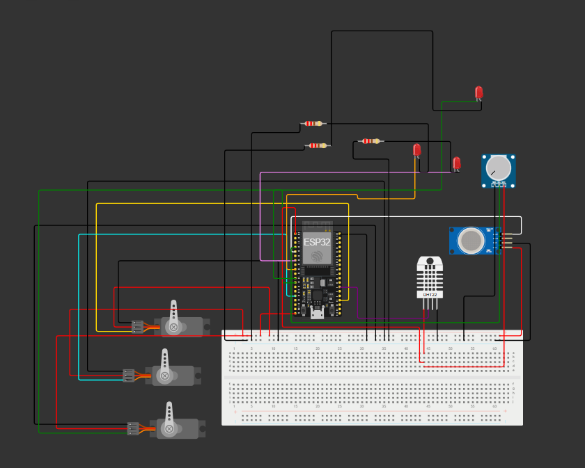
Circuit diagram simulated in Wokwi
The Smart Compost Bin circuit is built around an ESP32 Dev Board that controls all sensors and actuators:
Sensors
DHT22 measures temperature and humidity of the composting chamber (Data → GPIO 4).
MQ2 Gas Sensor detects VOC/gas buildup (Analog → GPIO 34).
Potentiometer simulates the soil/moisture sensor for testing (Analog → GPIO 39).
Actuators
3 Servo Motors (GPIO 15, 13, 14) control lids for transferring waste between layers.
Mixer Motor, Exhaust Fan, and Relay Output are simulated using LEDs:
LED on GPIO 25 → Mixer Motor ON/OFF
LED on GPIO 27 → Exhaust Fan (always ON in code)
LED on GPIO 32 → Relay Signal (simulates auxiliary control)
Power Connections
ESP32 VIN/5V → Red rail (Powers servos, MQ2, DHT, and LEDs)
ESP32 GND → Black rail (Common ground for all components)
Potentiometer powered from 3.3 V for stable analog input
Simulation Note
LEDs are used in place of DC motors, exhaust fan, and relay module since Wokwi does not support these components.
In real hardware:
GPIO 25 drives Mixer Motor via L298N
GPIO 27 drives Exhaust Fan via L298N
GPIO 32 controls Relay Module


_3u05Tpwasz.png?auto=compress%2Cformat&w=40&h=40&fit=fillmax&bg=fff&dpr=2)
Comments