


Hardware components | ||||||
 |
| × | 1 | |||
| × | 1 | ||||
| × | 1 | ||||
| × | 1 | ||||
| × | 1 | ||||
 |
| × | 1 | |||
| × | 1 | ||||
| × | 1 | ||||
Software apps and online services | ||||||
 |
| |||||
Hand tools and fabrication machines | ||||||
| ||||||
| ||||||
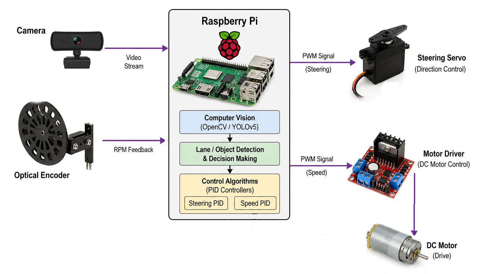
This project was developed as the final project for ELEC 553. The objective was to design and implement an autonomous vehicle capable of navigating a predefined track using computer vision and control techniques.
The system uses OpenCV-based image processing to detect lane markings in real time and estimate the vehicle’s trajectory. Based on this information, a steering angle is computed to keep the car aligned with the center of the track, and a PID controller is used to ensure smooth and stable steering behavior.
The electronics components are placed on top of the robot frame. Additionally, we created a 3D-printed camera mounting to adjust the angle more easily and robustly. As for the motor encoder, we placed it on the back of the car. low the track autonomously, with reliable performance in both straightaways and curves.
Hardware SetupThe electronics components are placed on top of the robot frame. Additionally, we created a 3D-printed camera mounting to adjust the angle more easily and robustly. As for the motor encoder, we placed it on the back of the car.
The system is running on Raspberry PI 4B with Raspbian Bookworm. On top of the kernel, we implement an encoder module to count pulses and calculate RPM. Rest of the program is running on application layer, which mainly running with Python programming language and some library dependencies, including OpenCV, Matplotlib, and YOLOv5.
Lane DetectionThe vehicle follows a track marked with blue tape, which is detected using a vision-based pipeline implemented in OpenCV. Each camera frame is first converted to the HSV color space, enabling robust color segmentation under varying lighting conditions. A mask is then applied to isolate the blue regions corresponding to the lane markings, and a region of interest (ROI) is defined to focus on the lower portion of the image where the track is expected.
From the masked image, the coordinates of the detected pixels are extracted and used to estimate the lane geometry. When both left and right lane boundaries are visible, a second-order polynomial is fitted to each side, and the center trajectory is computed as the average of both curves.
Finally, this centerline is used to compute a steering angle, which the control system later uses to adjust the vehicle’s direction.
Steering and Speed PID ControlThe vehicle's steering is controlled by a PID controller that takes as input the difference between the desired heading (straight ahead) and the angle estimated by the vision system. This error is used to compute a correction, which is mapped to a PWM signal that drives the steering servo.
For speed control, an optical encoder measures the motor's rotational velocity in real time. This feedback enables a closed-loop PID controller to regulate the vehicle’s speed by adjusting the motor's PWM signal, maintaining a consistent velocity despite changes in load or track conditions.
The PID parameters were tuned experimentally through iterative testing. We first focused on tuning the steering controller by manually moving the robot around the tracks, followed by the speed controller. In both cases, performance was evaluated by analyzing plots of the measured values against the target and the corresponding errors over time, allowing us to refine the gains for stable, responsive behavior. Regarding the Kp, Ki, and Kd for each controller, we start by tuning Kp to achieve a fast response, then adjust Kd to correct the error, and adjust Ki when the plot shows too much oscillation.
In addition to lane tracking, the system detects red markers along the track, which serve as stop signals. These markers consist of red paper squares on the floor and are identified using color segmentation in the HSV color space. The total area of detected red pixels is used as a simple metric to determine when a marker is present.
When a red signal is detected above a predefined threshold, the vehicle initiates a stop. The first detected marker causes the car to stop temporarily, then resume motion. Upon detecting the second marker, the vehicle performs a complete stop, ending its operation. A flag-based approach ensures each marker is counted only once, preventing multiple detections of the same signal.
DemoLane Keeping and Stop DetectionThe robot demonstrates the capability to move along the lane without exceeding the lane by more than 6 inches. Furthermore, the robot stops at the first red box, continues moving until the second red box is detected, and thenfinishes the program. Additionally, we record the robot from both first- and third-person views.
Object RecognitionIn addition to lane tracking, we implemented object detection with YOLOv5 on the Raspberry Pi using the onboard camera. For this, we used the official Ultralytics repository and adapted it to our setup. Input images were resized to 320×320 pixels to balance detection performance and computational cost.
To estimate the system’s performance, we first evaluated inference on a single test image, measuring the time spent in preprocessing, model inference, and non-maximum suppression (NMS). This resulted in an approximate throughput of 3.8 FPS. While this value serves as a reference, actual performance during live streaming can vary due to additional latency, camera bottlenecks, and memory overhead.
Finally, we used the provided detect.py script from the repository to run the model and perform real-time object detection, as demonstrated in the accompanying video.
- User raja_961, “Autonomous Lane-Keeping Car Using Raspberry Pi and OpenCV”. Instructables. [Online]. Available: https://www.instructables.com/Autonomous-Lane-Keeping-Car-Using-Raspberry-Pi-and/
- J. Johnston, “Tutorial: Running YOLOv5 Machine Learning Detection on a Raspberry Pi 4, ” Medium, 2021. [Online]. Available: https://jordan-johnston271.medium.com/tutorial-running-yolov5-machine-learning-detection-on-a-raspberry-pi-4-3938add0f719
- G. Jocher, “YOLOv5 by Ultralytics, ” 2020. [Online]. Available: https://github.com/ultralytics/yolov5


Comments