


Hardware components | ||||||
 |
| × | 1 | |||
 |
| × | 1 | |||
 |
| × | 1 | |||
 |
| × | 1 | |||
Software apps and online services | ||||||
 |
| |||||
Hand tools and fabrication machines | ||||||
 |
| |||||
Smart posture corrector is a very useful device in the modern era. People are giving importance to health and wealth in current society, a smart posture corrector would correct the common mistakes we make while sitting or bending. These bad postures might cause backpain, fatigue etc. A good posture provides better spinal alignment. Here we use an MPU6050 sensor for the angle detection, an esp8266, a vibration motor for alert and a transistor.
Significance
Posture correctors are significant because they serve as a reminder to adopt and maintain better posture, which can alleviate back and shoulder pain, improve confidence, and prevent long-term musculoskeletal issues. By engaging the correct muscles and promoting muscle memory through consistent use, they help align the spine, lift the shoulders, and reduce strain, though they are not a substitute for dedicated physical therapy or treating serious medical conditions.
How Posture Correctors Work
Reminders for Alignment:
The primary function of a posture corrector is to provide feedback, whether through gentle tension or alerts. When you slouch, the device provides a reminder to sit up straight, helping your body learn what proper alignment feel like.
Muscle Activation:
The device encourages you to activate the muscles in your back and shoulders, promoting their proper function and strength over time.
Muscle Memory and Training:
Consistent, short-interval use helps train your muscles to hold a corrected posture even after the device is removed.
Components Needed
ESP8266
MPU6050 module
Buzzer / vibration motor
USB cable
wires
Estimated cost: ₹500–₹1000
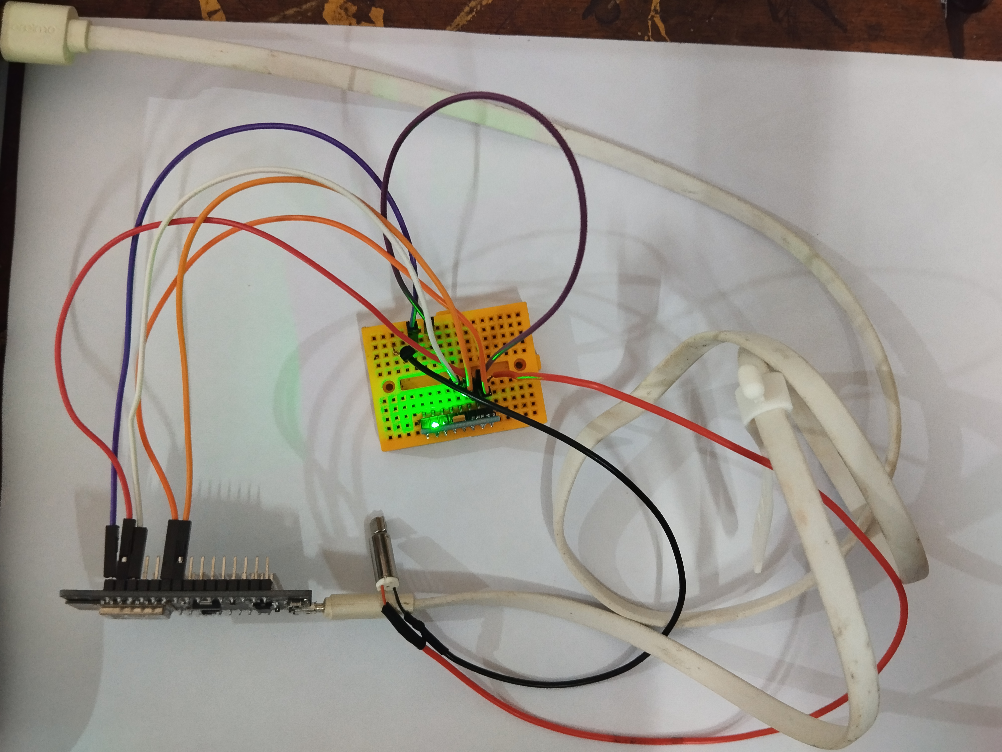
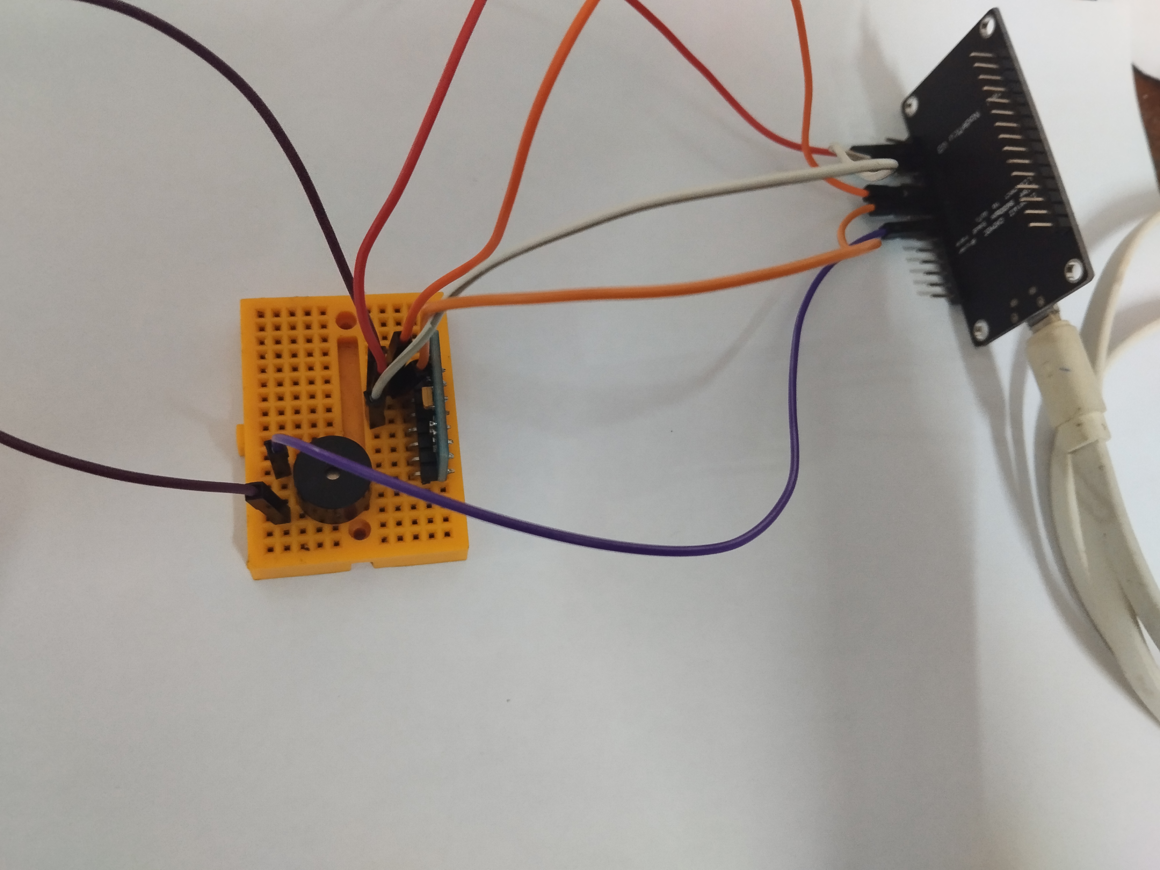
Hardware Setup & Wiring
Pin Mapping
GPIO4 (D2)→ MPU6050 SDA
GPIO5 (D1)→ MPU6050 SCL
GPIO12 (D6)→ Buzzer output
3.3 V→ MPU6050 VCC
GND→ Common ground (ESP, MPU6050, buzzer)
Note: Ensure the USB cable powers only the ESP8266 board; do not attempt to drive the motor from the USB 5 V pin directly.
Step‑by‑Step Assembly
1. Connect the MPU6050 via I²C on pins D2 (SDA) and D1 (SCL).
2. Attach the buzzer to GPIO12 ; connect its other pin to GND.
3. Mount the sensor on upper back (strap or clip) so its X‑axis points forward.
4. Connect the ESP8266 to your PC via USB**. It will power everything.
5. Install Arduino IDE, add the **Boards Manager support for ESP8266/Kaspar or NodeMCU**, and install libraries: *Adafruit\_MPU6050*, *Adafruit\_Sensor*.
Calibration & Testing Procedure
Anchor your setup in this order:
a) Upload the code (see attachments).
b) Open **Serial Monitor at 115200 baud**.
c) Hold the device upright for \~2 seconds after power-up. The sketch auto-calibrates the **baseline angle**.
d) Tilt slowly forward ≥25°—Serial should show increasing angle.
e) Hold tilt > threshold for \~2 seconds to trigger buzzer.
f) Straighten posture to stop buzzer.
Quick Troubleshooting Tips
'415° Serial prints': means your MPU6050 modules are rotated 90°—swap -a.acceleration.x to a.acceleration.y
Buzzer never sounds: check whether it's an **active buzzer** vs passive; ensure your GPIO can deliver a few mA (≤12 mA safe) .
Pitch reads constantly zero or ±90: run test prints on raw `a.x, a.z' if they’re ±0.0/±1.0 only, sensor may be wired to wrong pins.: run test prints on raw `a.x, a.z`—if they’re ±0.0/±1.0 only, sensor may be wired to wrong pins.
Motor buzzing intermittently: angle is very noisy—implement a smoothing filter or increase delay.
You now have a complete, streamlined version of your posture-corrector wearable, with no external power, no driver circuits and all key logic embedded in the ESP8266. It’s perfect for expo demos or early prototypes.
Hardware is minimal and wearable.
Code uses safe current limits and simple calibration.
References
Advanced Posture Corrector
The device can undergo next level techniques including wireless connectivity by using Blynk. Device can be run battery powered by using LiPo (Lithium-polymer) cells.
Future Proofing of Our Device
For the students, technophiles or techies of the current world who spend hours hunched over a keyboard, staring at the screen, tapping away and resulting in bad posture that's where posture corrector is used.
The Posture Corrector in the long run can be modified as wireless battery powered automatic device. Use of more advanced sensors enable a quick and sharp real time analysis.
This device can be customized based on the height of people (as the bending or bad posture may vary with the height) and can be integrated with other health monitoring systems which provide more comprehensive understanding of the user's overall health.
Conclusion
The posture corrector presented here demonstrates how a simple yet effective wearable can be built using minimal hardware and embedded logic within the ESP8266. By combining the MPU6050 sensor with a buzzer alert system, users receive instant feedback whenever poor posture is detected. The troubleshooting measures and calibration methods ensure reliability and ease of replication, making this prototype ideal for demonstrations, academic projects, or personal use.
Looking ahead, the device can be further enhanced with wireless connectivity, battery-powered operation, and integration of advanced sensors for more accurate posture tracking. With these improvements, the posture corrector has the potential to evolve into a smart, user-friendly health monitoring tool that not only corrects posture but also contributes to overall well-being.


Comments