

Hardware components | ||||||
 |
| × | 1 | |||
 |
| × | 1 | |||
| × | 1 | ||||
 |
| × | 1 | |||
 |
| × | 1 | |||
 |
| × | 2 | |||
 |
| × | 2 | |||
Software apps and online services | ||||||
 |
| |||||
 |
| |||||
Hand tools and fabrication machines | ||||||
 |
| |||||
 |
| |||||
This application creates a simple proximity metal detector with the Core Independent Peripherals (CIPs) in the PIC18-Q71 family of microcontrollers (MCUs) to differentiate between metallic and non-metallic objects placed near the detector coil. The CIPs are built into the die of the microcontroller to reduce the number of external components needed and the design area, all while increasing the functionality of the device.
Theory of OperationIn short, this application works by detecting a change in the damping time of an LC resonant network (composed of an inductor and capacitor in parallel). Metal near the inductor creates eddy currents from the inductor’s magnetic field, which causes the LC network to damp faster than if a non-metallic object (or air) was placed nearby.
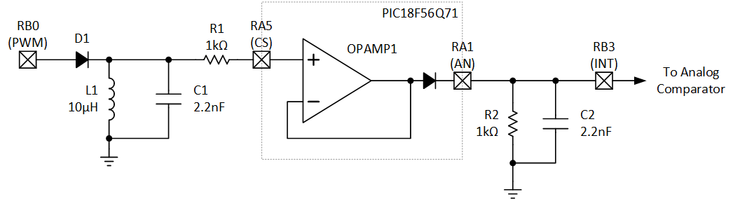
First, let’s look at the LC tank. To generate ringing, a Pulse-Width Modulated (PWM) waveform is applied to the resonant tank. The PWM duty cycle is set to half the period of the resonant frequency, to avoid dissipating excessive power and to increase time for the tank to ring between pulses. The pulses are then passed through a diode to protect the microcontroller I/O and to avoid dissipating the energy applied to the tank. A current-limiting resistor connects the LC tank to one of the Operational Amplifier (OPAMP) inputs on the microcontroller. This resistor (R1) is crucial to the design, as it reduces the current through the diodes to a safe level. Without it, the electro-static discharge (ESD) diodes inside the I/O would normally short the negative pulses to ground, dissipating the energy, potentially damaging the microcontroller. R1 reduces the current through the diodes to a safe level.
The internal OPAMP of the microcontroller is set up in a unity gain configuration with a peak detector. The peak detector adds an internal diode to the output of the OPAMP, allowing the OPAMP to only drive the output if the RC network is at a lower voltage.
On the output I/O is an RC resonant circuit. Ordinarily, directly driving a capacitor with an OPAMP would not be recommended, but in this case, the circuit is acceptable due to the peak detector configuration.
This RC network is charged by the OPAMP and is constantly discharging through the resistor in parallel with the capacitor. As the LC tank resonates, the peaks of the LC resonance cause the OPAMP to momentarily recharge the RC network when the LC voltage is above the RC voltage, which stretches the time out.
Now, to detect metal, the microcontroller uses an internal Analog Comparator (CMP) to measure the discharge time of the RC network to a known voltage set by the Digital-to-Analog Converter (DAC). Discharge time is calibrated on start-up.
Setting Up the Metal DetectorBuild the following circuit on a Proto Click™ from MikroE. For D1, we used a 1N4148 diode.
With the power off, plug the assembled Proto Click into Socket 1 on the Curiosity Adapter Board (AC164162). Then, plug in the PIC18F56Q71 Curiosity Nano (EV01G21A) into the MCU socket. Connect the Curiosity Nano to your computer with a USB cable. The Nano can be programmed through MPLAB® X IDE or by dragging and dropping a compiled hex file onto the Nano in File Explorer (it appears as a USB drive in Windows Explorer).
Using the ApplicationOn startup, the application performs self-calibration. During this time, metal should be kept away from the inductor (or coil) for increased sensitivity. The LED will blink while this is active.
After calibration, the LED on the Curiosity Nano (LED0) will stop blinking and will turn ON/OFF depending on if metal is detected nearby.
Teodor-Emilian Petre
 Robert Perkel


Comments