

Hardware components | ||||||
 |
| × | 1 | |||
 |
| × | 1 | |||
 |
| × | 1 | |||
Software apps and online services | ||||||
 |
| |||||
Hand tools and fabrication machines | ||||||
 |
| |||||
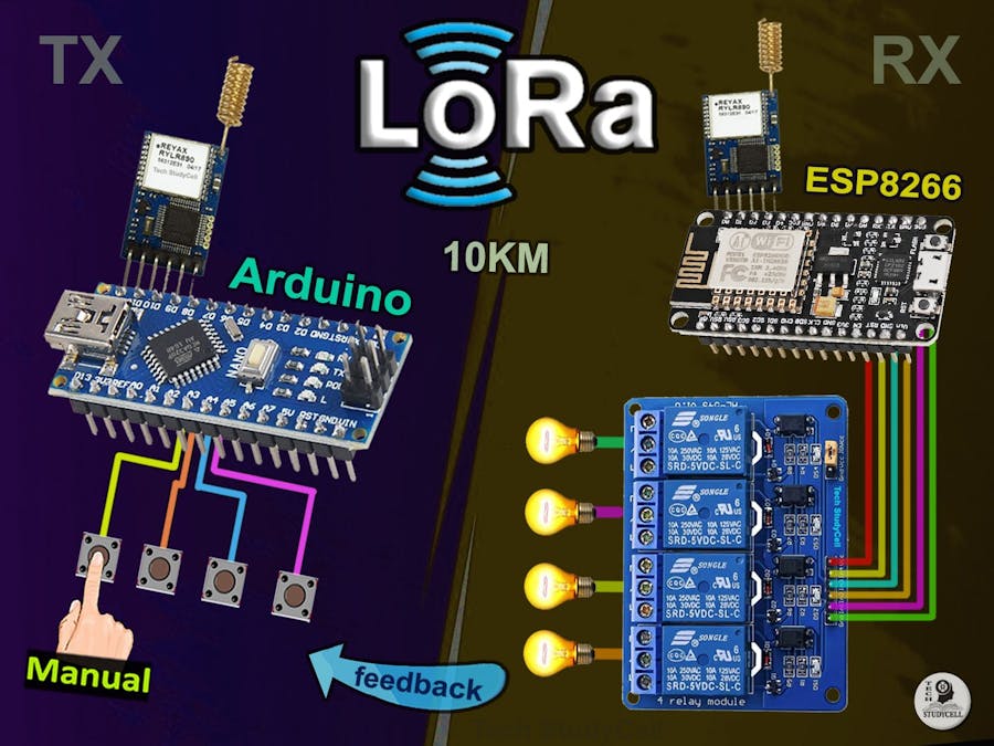
In this Lora project tutorial, I have shown how to make the LoRa Arduino ESP8266 control relay using the RYLR896 LoRa module with real-time feedback.
So after turning on and off the appliances the receiver circuit will send feedback to the transmitter circuit.
Tutorial Video on the LoRa ProjectIn this video, I have covered the following topics.
- Explained this ESP8266 Arduino Lora home automation project.
- Explained Transmitter & Receiver Lora circuit.
- Configure LoRa with AT commands.
- Explained the source codes for this LoRA project.
- Connecting the LoRa module with Arduino and ESP8266.
- Control high voltage appliances with LoRa.
So if you follow all the steps, you can easily make this Lora Arduino project to control any appliances from 10KM away in the rural areas without Wi-Fi and Bluetooth. So this project is very useful in rural areas.
Although the PCB is not mandatory, however, if you want, you can also use this PCB to make the circuit compact and give the project a professional look.
Required component for this Transmitter circuit- REYAX RYLR896 Lora Module
- Arduino Nano
- 220-ohm Resistor
- 4.7k Resistor
- 10k Resistor
- 5-mm LED 3no
- Push buttons 4no
- REYAX RYLR896 Lora Module
- ESP8266 NodeMCU
- 5v 4-channel Relay Module
- 4.7k Resistor
- 10k Resistor
1. Relays 5v (SPDT) (4 no)
2. BC547 Transistors (4 no)
3. PC817 Optocuplors (4 no)
4. 510-ohm 0.25-watt Resistor (4 no) (R1 - R4)
5. 1k 0.25-watt Resistors (5 no) (R5 - R9)
6. LED 5-mm (5 no)
7. 1N4007 Diodes (5 no) (D1 - D5)
8. Push Buttons (4 no)
9. Terminal Connectors
10. 5V DC supply
Required Software:1. Arduino IDE
Transmitter Lora Circuit Using ArduinoIn the transmitter LoRa circuit, I have used Arduino Nano. I have made a voltage divider using 4.7k and 10k resistors to drop down the 5-volt logic level to the 3.3-volt logic level.
The pushbuttons are connected with the D2, D3, D4, and D5 digital pins of the Arduino.
I have used the INPUT_PULLUP function in Arduino IDE instead of using the pull-up resistors.
And the LEDs are connected with the D7, D8, and D13 digital pins of the Arduino.
On the Arduino board, a resistor is already connected in series with theD13 pin, so I have not used any series resistor with the LED for the D13 pin.
You can use any 5V DC supply or 9V battery to supply the circuit.
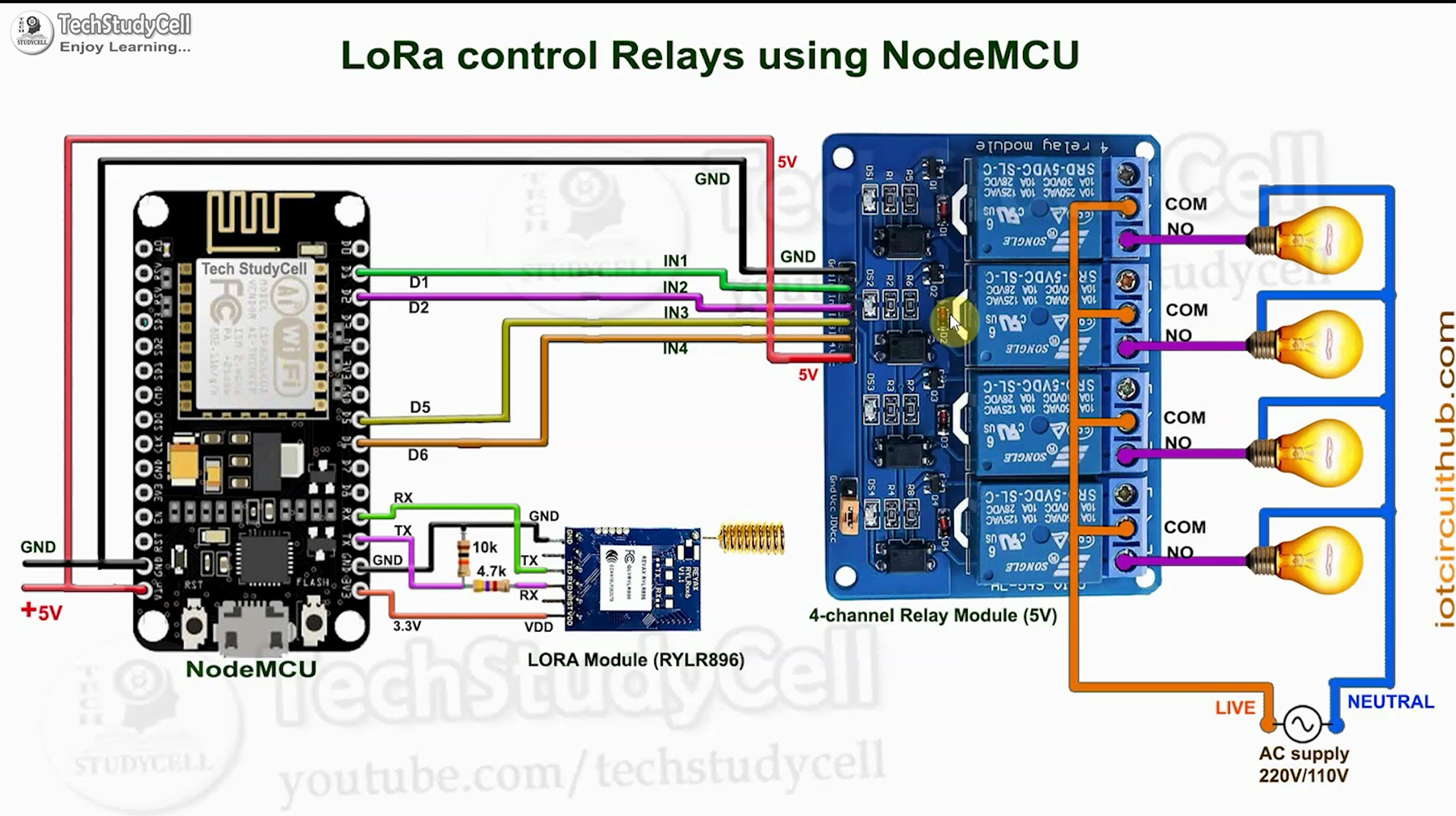
Receiver Lora Circuit Using ArduinoIn the receiver LoRa circuit, I have used NodeMCU as the microcontroller. In the circuit, I have also made a voltage divider using 4.7k and 10k resistors to drop down the 5-volt logic level to the 3.3-volt logic level.
I have used D1, D2, D5 & D6 GPIO pins to control the 4 relays.
**The Boot will fail if RX is grounded during the Boot process of NodeMCU. So, connect the LoRa module after giving the supply to NodeMCU.
I have used a 5V 2Amp power supply to supply the NodeMCU and relay module.
Please take the proper safety precautions while working with high voltage.
Configuring the Parameters With AT CommandsFirst, you have to connect the LoRa module with FTDI232 USB to serial interface board as per the circuit to configure some parameters with AT commands.
In Serial monitor select the Baud rate = 115200 and "Both NL & CR".
AT Commands used for the Transmitter LoRa module
- AT+ADDRESS=1
- AT+NETWORKID=5
- AT+BAND=865000000
AT Commands used for the Receiver LoRa module
- AT+ADDRESS=1
- AT+NETWORKID=5
- AT+BAND=865000000
Select the BAND as per the eligible LoRa bands available in your country.
Please refer to the tutorial video for more details.
Codes for This LoRa Project Using Arduino and ESP8266In this Lora Project, I have used Arduino Nano for the transmitter circuit, and NodeMCU for the receiving circuit.
First, download the source codes. Then upload the code for the transmitter circuit to Arduino. And upload the code of the receiving circuit to NodeMCU.
Design the PCB for the Receiving LoRa CircuitTo make the circuit compact and give a professional look, I have designed the PCB after testing all the features of the smart relay module.
You can download the PCB Gerber file of this home automation project from the following link:
https://drive.google.com/uc?export=download&id=1Jx4D_DSV_ei1y0a82AbtxbsNhy8sjCmY
Order the PCBAfter downloading the Garber file you can easily order the PCB
1. Visit https://jlcpcb.com and Sign in / Sign up
2. Click on the QUOTE NOW button.
3. Click on the "Add your Gerber file" button. Then browse and select the Gerber file you have downloaded.
Uploading the Gerber File and Set the Parameters4. Set the required parameter like Quantity, PCB masking color, etc.
5. After selecting all the Parameters for PCB click on SAVE TO CART button.
Select Shipping Address and Payment Mode6. Type the Shipping Address.
7. Select the Shipping Method suitable for you.
8. Submit the order and proceed with the payment.
You can also track your order from the JLCPCB
My PCBs took 2 days to get manufactured and arrived within a week using the DHL delivery option.
PCBs were well packed and the quality was really good at this affordable price.
Solder All the Components on PCBAfter that, I have soldered all the components as per the circuit diagram.
Then connect the NodeMCU board with the PCB.
Connect the Appliances With the Relay ModuleConnect the 4 appliances with the relay module as per the circuit diagram.
Please take proper safety precautions while working with high voltage.
Connect the LoRa Module With Arduino and ESP8266After uploading the codes, connect the LoRa modules with the Arduino and NodeMCU.
For the receiving circuit turn ON the 5V supply before connecting the LoRa module.
Control the Appliances With LoRaNow you can control the appliances with the transmitter LoRa circuit and also monitor the real-time feedback from the receiver LoRa circuit.
Please make sure there should not be any loose connection, otherwise, this circuit may not work.
In the future, I will try to add more features to this LoRa project.
I will really appreciate it if you share your valuable feedbacks. Also if you have any query please write in the comment section.
Thank you & Happy Learning.


Comments