


Hardware components | ||||||
 |
| × | 1 | |||
| × | 1 | ||||
| × | 1 | ||||
| × | 1 | ||||
 |
| × | 1 | |||
| × | 1 | ||||
| × | 1 | ||||
Software apps and online services | ||||||
 |
| |||||
| ||||||
| ||||||
| ||||||
 |
| |||||
 |
| |||||
Hand tools and fabrication machines | ||||||
 |
| |||||
<Quick Guide>


Required items
: Components listed in the BOM, computer, Arduino App Lab, Arduino IDE, microSD card with at least 16GB capacity, microSD card reader, USB-C cable capable of data transfer, Wi-Fi router or mobile hotspot, Hugging Face API key

1. Nextion Display Setup
   1) Upload the .tft file from the nextion folder on the GitHub page to the SD card.
   2) Insert the SD card into the back of the Nextion display.
   3) Supply 5V, 1A power to the display with the SD card inserted (the UNO Q's 5V and GND pins are recommended).
   4) The .tft file will automatically upload to the display.
   5) Once the upload reaches 100%, disconnect and reconnect the power.

2. Core Setup
   1) Download the entire nli 0.1.5 folder from the GitHub page as a single folder.
   2) Launch Arduino App Lab, connect the Arduino UNO Q to your computer, and establish a connection.
   3) Click "+ Create app" in the upper-right corner, then click "import" to upload the entire nli 0.1.5 folder.
   4) Configure the UNO Q's Wi-Fi connection.
   5) Default settings
   6) AI API setup
      6_1) Create a Hugging Face account.
      6_2) Open Settings from your profile in the upper-right corner.
      6_3) Set up payment under the Billing tab (or use the free trial).
      6_4) Generate and copy an API key under Access Tokens (Caution! Do not enter your API key into an AI or reveal it to anyone! This is an important security precaution!).
      6_5) Return to the project in App Lab and paste the API key into hf_token.txt in the secrets folder.
   7) Module function setup
      7_1) Define your robot's name and what each function will do.
      7_2) Enter your robot module's name, functions, and a description of each function in module_knowledge.csv in the knowledge folder, following the specified format. (Examples are provided in the file.) (The AI will use this file to respond and control the robot.)
      7_3) If you use a variable Function that includes numbers, clearly define the position and meaning of each number in the description in the .csv file.

3. Module Setup
   1) Download esp_AQ_wifi_en.ino from the esp_AQ_wifi_en folder on the GitHub page.
   2) Open esp_AQ_wifi_en.ino in the Arduino IDE.
   3) Go to File → Preferences → Additional Boards Manager URLs and enter https://raw.githubusercontent.com/espressif/arduino-esp32/gh-pages/package_esp32_index.json
   4) Install Adafruit BusIO (Adafruit BusIO by Adafruit) from Tools → Board → Library Manager.
   5) esp32
   6) Enter the Wi-Fi credentials you will primarily use in the WIFI_SSID and WIFI_PASSWORD variables in the code.
   7) This code is a basic communication example, so you can modify it to suit your needs. (Coding guidelines are provided below.)
      7_1) ★ Your code must control the modules based on the Function names registered in module_knowledge.csv on the Arduino UNO Q.
      7_2) Do not arbitrarily use commands or names in the module code that differ from the Name and Function entries in module_knowledge.csv.
      7_3) When the core and module first communicate, generate an I-type code and send it to the core so that the core can identify which module is currently connected.
      7_4) Set the module ID so that it does not duplicate another module's ID.

4. Core - Module Communication
   1) Turn on the core and module.
   2) Check that the core and module are connected to the same Wi-Fi network.
   3) Check the module's TCP/IP address in the Arduino IDE.
   4) Wait for the device to say "activated".
   5) Tap the blank area at the bottom left of the screen, tap the IP address input field, and enter the module's TCP/IP address.
6) Once the connection is confirmed, you can start using the system.Today’s homes are rapidly filling with a variety of smart devices, such as robot vacuum cleaners, smart lights, air purifiers, and temperature and humidity control devices. In the past, many restrictive smart home services offered only limited support for appliances from other manufacturers, which posed a problem. Recently, however, the emergence of universal smart home standards such as Matter has increasingly enabled devices from different manufacturers to connect and operate within a single ecosystem.
However, we focused on a different question: Is enabling devices to connect with one another the same as enabling users to interact with them easily and naturally?
In today’s smart homes, users often still need to know which device is required to accomplish a task and decide which function to activate. For example, when a room feels stuffy, users must turn on an air purifier, activate a ventilation system, or open the relevant application themselves. If cleaning is needed, they must select and start the robot vacuum cleaner themselves. In other words, as smart home technology advances, connectivity between devices continues to improve, but a step still remains between human intent and the actions of actual devices. This is where the idea for Bunee began.
“What if users could simply express what they wanted naturally, without having to think about which device to use, and a robot could respond accordingly?”
Starting with this question, we set out to create Bunee, an AI-based modular home service robot platform.
Bunee’s goal is not to create a new smart home communication standard. Nor is it intended to replace existing smart devices or IoT environments. Instead, Bunee aims to provide an intelligent interface that bridges users’ natural language and behavior with the actions of actual devices.
Another important consideration was that users should be able to configure the system themselves to suit their own environments. Not every household uses the same devices, and not every user needs the same functions. Therefore, we designed Bunee as an open system in which users can register the devices they want to use, assign functions and IP addresses to each device, and add them as devices that Bunee can control and operate as desired, rather than as a closed system that controls only a few predefined devices. The main functions we aimed to implement were as follows..
- Listen to users and understand their intent.
- Recognize users’ facial expressions through a camera to understand their situation-
- Activate modules that match users’ intent and respond with appropriate speech and facial expressions.
- Allow users to assign module IP addresses and define their functions themselves.
To implement this, we decided to use the Arduino UNO Q at the center of the system, as the core. When a user tells Bunee what they want in natural language, the Core uses NLI to interpret the user’s intent, checks the connected modules and their functions, and determines the appropriate action.
For example, if a user says,“Bunee, I want to clean the room.”
Bunee does more than simply map a specific voice command to a button action; it interprets the user’s request as an intention related to cleaning. It then selects a module capable of performing the task from among the currently connected modules and sends a command to operate the actual device. Through this approach, we aimed to go a step beyond conventional command-based smart home control and implement intent-based interaction, in which users express their desired goals and the system selects the appropriate functions.
Another key feature of Bunee is its modular architecture.An approach that integrates all functions into a single robot in a fixed configuration makes it difficult to accommodate diverse environments, because users need different smart home functions and use different devices. It also has environmental drawbacks, as it requires the inclusion of unused functions and modifications to the entire system whenever a new function is needed. With the Bunee Module approach we adopted, users can add the necessary Module when a new function is needed instead of redesigning the entire robot. Existing network devices can also be added to Bunee’s control by allowing users to register their functions and connection information themselves. We also designed the system to support expansion through the addition of new modules when new functions are needed, rather than requiring the entire robot to be redesigned.
1. System ArchitectureOverall, the basic operating structure of Bunee that we designed is as follows.
Bunee consists of a Core that receives and processes user requests, an AI LLM that interprets natural language, and a Module that performs the actual tasks.
Also in detail, Software Architecture is like below.
The robot system in this project consists of three entities: the Core, which handles central control; a Hugging Face-based AI LLM, which interprets natural language and makes decisions; and the Module, which performs the actual actions. The Core collects and processes the user's voice commands, facial expressions, and status information from each module, then passes this information to the LLM. Based on this input, the LLM determines the user's intent and generates appropriate control commands. The generated results are sent back to the Core, which converts them into this project's communication format and finally sends the commands to the corresponding Module.
On the UNO Q, Python handles speech processing, facial image inference, local information retrieval, HTTP-based AI requests, and TCP communication. C++ exchanges data with Python through Arduino Bridge and manages Nextion UART communication and display states. Connecting AI services and physical device interfaces within the same core is central to how we use the board.
To achieve this, we implemented bidirectional communication between the Core, LLM, and Module, designing the system to process the user's natural language input and facial expression information, module status reports, AI decisions, and actual control commands within a single communication flow. In this structure, the central Core acts as a relay and control hub between the user and the robot hardware, translating AI decisions into actual robot actions.
2. BOM<Core Components>1. Arduino UNO Q
5. Webcam
6. Arduino USB Type-C Cable 2-in1
8. Filament
<Module Components>1. ESP32-WROOM-32
5. XL6009E1 DC-DC Adjustable Step Up
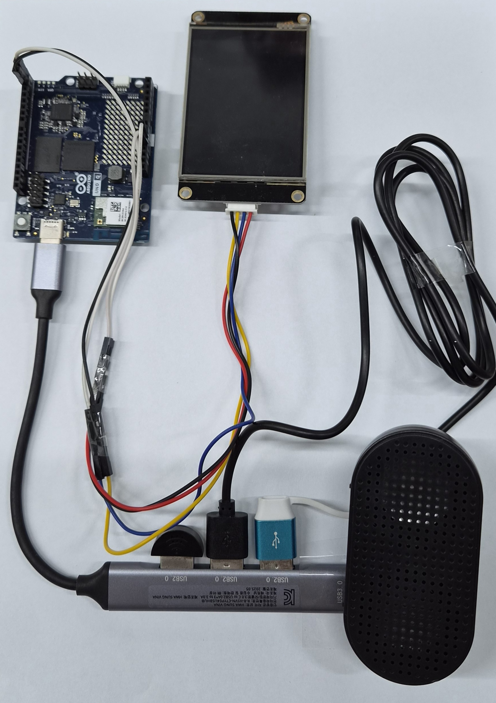
The core system is structured around the Arduino UNO Q, connecting peripherals and a display through a USB hub. Since the speaker and microphone are USB-based devices, they can be easily connected simply by plugging them into the USB hub. The ESP32-CAM module is also connected to the hub via a USB cable, and the hub itself connects to the USB-C port of the UNO Q. A 5V 3A power supply is connected to the external power input of the hub.
The display is connected to the UNO Q using power and communication lines. For power, it connects to the 5V and GND pins. The communication lines are cross-connected: the TX of the UNO Q to the RX of the display, and the RX of the UNO Q to the TX of the display. Through this UART communication, the display receives control signals from the UNO Q.
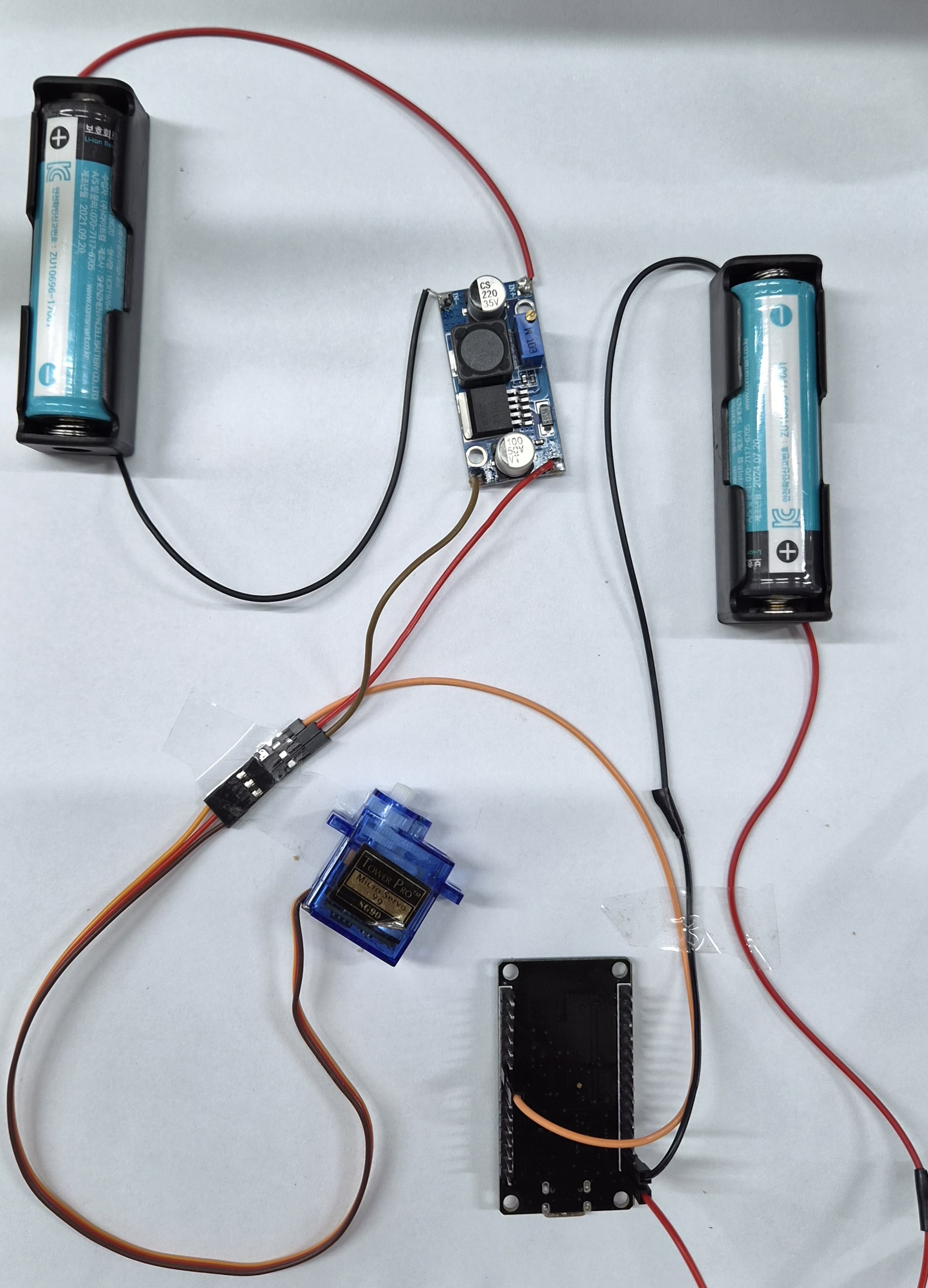
The module system is structured around the ESP32-WROOM-32, connecting an SG90 servo motor and batteries. The ESP32 and the servo motor are powered by separate 18650 batteries respectively, and the servo motor is driven by control signals output from the ESP32.
For the servo motor battery, the positive and negative terminals are connected to the IN+ and IN− of the boost converter, respectively. The output voltage of the converter is set to 5V, with OUT+ connected to the power line of the servo motor and OUT− connected to its GND line. This steps up the battery voltage to supply the power required to drive the servo motor.
The signal line of the servo motor is connected to the GPIO pin specified in the ESP32 control code. Additionally, the GND of the ESP32 is connected to the OUT− of the converter and the GND of the servo motor to establish a common ground. This connection allows the ESP32 and the servo motor to share the same reference voltage, enabling control of the servo motor's rotation angle based on the control signals delivered by the ESP32.
4. Assembly instructionsPosition the display and speaker so that they align with the openings in the main body.
Attach the Arduino UNO Q to the cover.
Connect the microphone and speaker to the USB hub connected to the Arduino UNO Q, and connect the Nextion display to the Arduino UNO Q as well.
Connect a 5V 3A power supply and add decorations.
5.How it worksThis work consists of and operates through a total of three components. They can be broadly classified into three categories: core, camera, and module.
5.1 Overall SystemAI that understands natural language and physical robot hardware use different information formats and command systems. Connecting the two systems directly can therefore lead to uncertainty in command interpretation or differences in communication methods between modules. In particular, controlling robot modules with various functions through a single AI system requires a common representation that bridges AI decisions and executable hardware commands.
To address this, we designed a custom code protocol that can be shared by the Core, AI LLM, and Module. This code is not conventional program source code, but a structured communication format for transmitting commands, status, Functions, and data according to consistent rules. Messages use the template [①|②|③|④|⑤|⑥], with each field assigned a role such as message type, Module identifier, Function, Parameter, status information, or additional data. This allows information exchanged between different systems to be expressed in a common format.
The main feature of this protocol is its semi-structured template: the message structure remains fixed, while the values within it can be generated dynamically according to the situation. In a conventional fixed Function Calling approach, executable Functions are defined individually in advance, and the AI selects one of them. In our system, however, generation rules are defined alongside the Function descriptions registered for each Module, allowing the LLM to generate parts of a Function or Parameter directly from the user's natural language command within the limits permitted by those rules.
For example, the following Functions can be registered for a wheel Module.
CWXX : Rotate clockwise for XX seconds. Enter the rotation duration in seconds as a number in XX.
CCWXX : Rotate counterclockwise for XX seconds. Enter the rotation duration in seconds as a number in XX.
If the user commands, “Rotate clockwise for 7 seconds, ” the LLM interprets the rules in the Function description and the user's intent to dynamically generate the Function CW07. In a conventional fixed approach, Functions for each possible rotation duration, such as CW01, CW02, and CW03, must be registered individually. In our system, a single Function template, CWXX, can represent various duration values.
In this way, the protocol combines a fixed format that machines can reliably interpret with the flexible reasoning and generation capabilities of generative AI. It is designed to reduce the number of Functions that need to be registered and the complexity of Module configuration, while flexibly accommodating various natural language commands and new robot functions.
The basic format is as follows.
[①|②|③|④|⑤|⑥]
- ① Code Type ode의 목적과 통신 방향을 구분함. I : (InIdentifies the purpose and communication direction of the Code.I : (Initial) The Module declares its type and functions when it first connects.R : (Report) The Module reports its current status to the Core.O : (Order) The Core sends an execution command to an external Module.none : A response from the Core itself that does not control an external Module
- ② Module IDThe identifier of the target Module or the Module that provided the information.Example : MOTOR01, ARM01, WHEEL01
- ③ Function / Status Its meaning varies depending on the Type in ①.I Type : Declares the Module type and available FunctionsR Type : The Module's current statusO Type : The Function or Command to be executed by the Modulenone Type : none
- ④ Emotion / Robot FaceIts meaning differs between input and output.In input Codes such as I and R, it represents the user's facial expression recognized by the Camera.In AI output Codes such as O and none, it represents the facial expression command for the robot.Output can use NORMAL, SMILE, ANGRY, THINK, VERY_ANGRY, DIZZY, or the MANUAL:... format.
- ⑤ User UtteranceStores what the user said to the robot.Natural language recognized through STT is entered in this field.
- ⑥ Narration Stores what the Core will say to the user.This Text is output through the Speaker using TTS and simultaneously displayed on Nextion.
For example, suppose a Motor Module has reported that it is currently stopped using
[R|MOTOR01|STOPPED|neutral||]and the user says “Rotate clockwise for 7 seconds.”
Python combines the STT result and the user's facial expression to construct
[R|MOTOR01|STOPPED|neutral|시계 방향으로 7초 돌려줘|]as the AI input Code. Referring to the currently connected Module and its Function information, the LLM can generate an output Code such as
[O|MOTOR01|CW07|SMILE|시계 방향으로 7초 돌려줘|7초 동안 회전하겠습니다.]Then, CW07 in ③ is used for Module control, SMILE in ④ for robot face control, and Narration in ⑥ for TTS and display output. Throughout this process, the NLI Code serves as a common intermediate representation connecting the user's natural language to actual robot control.
5.2 DisplayThe Nextion Display handles the robot's facial expressions and user interface. Its main functions include facial expression animations, mouth movements linked to TTS, Narration display, Recording status display, an NLI Code Monitor, and TCP IP settings.
When Partition ④ of the LLM output Code contains a facial expression command such as SMILE, ANGRY, or THINK, Python passes it to C++, which converts the value into Nextion's face_exp variable. Nextion uses the received value to run its internal Timer and Animation Logic, moving the actual graphics, such as the eyes and mouth. Rather than having Arduino Q transmit coordinates for every frame, the system sends only the facial expression state and lets Nextion handle the animation internally.
In addition to Preset expressions, the system supports Parameter-based control such as MANUAL:LX…, RX…, LY…, RY…. This allows individual settings for eye position and size, forehead details, and features below the eyes. The AI can also generate new combinations of facial expressions within the permitted Parameter ranges.
While TTS audio is actually playing, Python activates Nextion's mouth animation through C++. Since mouth_ani is enabled when audio playback begins and disabled when it ends, mouth movements are synchronized with the actual speech rather than with the moment the AI response is generated. Narration in ⑥ of the NLI Code is output through TTS and simultaneously displayed on the Nextion screen.
Nextion also includes a Monitor function that displays the [I|...], [R|...], [O|...], and [none|...] Codes currently being transmitted and received. This allows users to see what data is moving between the Core, Module, and AI. It also displays the Recording status during STT recording, while the settings screen allows users to enter the TCP IP address for communicating with an external Module. C++ reads the entered IP address and passes it to the Python TCP Client, so there is no need to edit the source code directly when the network changes.
<Python> Python is the central processing component of this project. It combines user input and Module status into a single NLI Code and then breaks down the AI-generated result into actual robot functions. Its main functions include Config management, STT, TTS, Camera- based recognition of the user's facial expression, Module registration and status storage, RAG-based Function retrieval, Hugging Face API communication, TCP Module communication, and C++ Bridge integration.
For STT, the user's voice is recorded through the Microphone, and RMS values are used to detect silence. When speech is detected, Speech-to-Text is performed, and the resulting Text is combined with the current Module's latest R Code and the user's facial expression recognized by the Camera. For example, if the existing status is
[R|MOTOR01|STOPPED|neutral||]and the user says, “Rotate clockwise for 7 seconds, ”
[R|MOTOR01|STOPPED|neutral|7초 동안 시계 방향으로 돌려줘|]is constructed as the AI input. For ordinary conversation without a Module status,
[R|none|none|neutral|안녕|]is used to maintain the same format.
The Camera continuously detects faces and classifies emotional states to maintain up-to- date information about the user's facial expression. This information is included in Partition ④ of the AI input Code. In the AI output Code, however, Partition ④ is used as the robot's facial expression command. Thus, the same Partition represents the user's facial expression at the input stage and the robot's facial expression at the output stage.
When an external Module first connects, its Module ID and function information are registered through an [I|...] Code. An [R|...] Code is stored as the Module's latest status and later combined with user commands so that the AI can also consider the current hardware state. The available Functions and descriptions for each Module are stored separately in Module Knowledge, and RAG provides only the necessary information to the LLM Context.
In particular, Functions do not have to be defined as completely fixed values. For example, if CWXX is defined as “Rotate clockwise for XX seconds, with the desired duration entered in XX, ” the LLM can generate CW07 from the user's command, “Rotate for 7 seconds.” Since CW01, CW02, CW03, and so on do not all need to be defined individually as in a conventional approach, a small number of Function Templates can represent a wide variety of commands. This is a semi-structured design in which the overall NLI Code format remains fixed, while the AI can generate the Function within it according to defined rules.
The Context sent to the Hugging Face LLM includes the System Message, currently connected Modules, Function information retrieved through RAG, recent conversation information, and the final NLI Code. The LLM generates an [O|...] Code when an external Module needs to operate, or a [none|...] Code when only ordinary conversation or a response from the Core itself is needed.
For example,
[R|MOTOR01|STOPPED|neutral|7초 동안 시계 방향으로 돌려줘|]as input can produce an output such as
[O|MOTOR01|CW07|SMILE|7초 동안 시계 방향으로 돌려줘|7초 동안 회전하겠습니다.]Python splits this back into six Partitions: ③ CW07 is passed to the Module through C++ and TCP, ④ SMILE is passed to Nextion through C++, and ⑥ Narration is used for TTS and Nextion Text output.
TTS converts ⑥ Narration into speech and plays it through the Speaker, while notifying C++ of the start and end of speech to synchronize Nextion's mouth animation. The TCP Client handles Socket communication with external Modules, receiving their I/R Codes and sending AI-determined Commands back to them.
In other words, the Python NLI Core is the project's central processing component. It combines the user's voice, facial expression, Module status, and Function information into a single [R|...] input Code, then breaks down the [O|...] or [none|...] Code generated by the Hugging Face LLM into Module actions, Robot Face, and Narration.
<C++>The C++ section serves as a Gateway that connects the Python NLI Core with the actual hardware. Its main functions are Arduino Bridge communication with Python, management of Module input and output Queues, Nextion UART communication, face and UI control, TCP IP reading, and Timer management.
When NLI Code in the form of [I|...] or [R|...] is received from an external Module, Python, which handles TCP communication, passes it to C++. C++ stores the received Code in the Input Queue and then sequentially sends it back to the Python NLI Core in the Main Loop. The reason for using a Queue is to prevent communication conflicts caused by overlapping RPC calls between Python and C++. At this stage, the complete format of the NLI Code is preserved, while the actual interpretation of each Partition is performed in Python.
Conversely, when the LLM generates Code such as [O|MOTOR01|CW07|SMILE|...|...], Python extracts only CW07 from Partition ③, which is required by the external Module, and passes it to C++. C++ stores the command in the Command Queue and, in the Main Loop, calls Python's TCP transmission function again to deliver it to the actual Module. C++ does not directly interpret the meaning of the CW07 Function and only serves to forward the command determined by the AI. Therefore, even when a new Function is added, there is no need to continuously add separate decision logic for that Function in C++.
C++ communicates directly with Nextion through Serial UART. When SMILE is delivered from Python, it is converted into the Nextion face_exp value, and in the case of a MANUAL command, each Parameter is separated and delivered to the corresponding variable. It also converts Narration, Recording status, Speaking status, and Code Monitor data into Nextion commands for output. Simple state controls, such as face expression duration or Narration display duration, are also managed using C++ Timers.
In other words, C++ is not the section that determines the meaning of NLI Code, but rather the communication and hardware control layer that delivers the results determined by Python to the actual Modules and Display.
The USB webcam is wired to Arduino Q through an externally powered USB-C hub. There is no wireless link or network streaming stage between the camera and the robot board — once the camera is plugged into the powered USB-C hub, Arduino Q recognizes it as a standard webcam device (the same hardware configuration). Arduino Q then reads frames from this camera one at a time via OpenCV for processing.
For each captured frame, Arduino Q first runs a face detection model to locate any faces present. This model identifies the position (bounding box) of each human face within the frame and converts the coordinates back to the original image's coordinate space. If multiple faces appear in a frame, all of their positions are detected. Among the detected faces, any face whose size is too small relative to the frame — for example, a person standing too far from the camera — is treated as low-confidence and discarded. This reduces false positives caused by small background regions that coincidentally resemble a face, or by faces that are too distant to analyze reliably.
Only the faces that pass this size filter are cropped and passed to the second AI model, the emotion classification model. This model analyzes the cropped face image and classifies it into the closest emotional state. The underlying model was trained to distinguish six fine-grained emotions (Joy, Flustered, Anger, Anxiety, Hurt, Sadness); however, for actual robot operation these are consolidated into three simplified categories — Joy, Anxious, and Sad. Flustered, Anger, and Anxiety are merged into "Anxious, " while Hurt and Sadness are merged into "Sad." This consolidation reflects the practical design decision that, for human-robot interaction, broad emotional categories are more useful than fine-grained distinctions the robot would otherwise need to react to individually.
For the emotion classification task, a convolutional neural network (CNN) architecture — ResNet18, a widely used model for image classification — is applied. A CNN is built from a stack of convolutional layers that scan the image with small filters (kernels) to extract basic visual features such as edges, lines, and color contrast; as the network goes deeper, it recognizes increasingly complex and abstract features, such as the shapes of the eyes, nose, and mouth, or overall facial expression patterns. Between convolutional layers, a pooling operation reduces the spatial size of the feature maps while retaining the most salient information, which lowers computational cost while preserving the essential structural information of the face. The extracted features are then passed to a final fully connected (classification) layer, which combines them to compute a score representing how closely the face matches each emotion class; this score is converted into a probability distribution, and the emotion with the highest probability is selected as the final prediction.
A single frame detecting a given emotion does not immediately confirm that result. An emotion is only confirmed once the same result is detected consistently across a defined number of consecutive frames, and only confirmed emotions are reported as final output. This consecutive-frame threshold can be adjusted directly by the user through a slider on the web interface, allowing sensitivity to be tuned to the environment or use case. The confirmation state resets whenever the face disappears from the frame. Once an emotion is confirmed, its label, confidence score, and timestamp are transmitted to the web interface and logged. Independently, the live camera feed is compressed and continuously streamed to the same interface at several frames per second, allowing the user to view the live video and the emotion recognition results simultaneously.
Model Training Process on Google Colab
The emotion classification model was trained separately in a Google Colab environment. The source training data consisted of human face photographs organized into folders by emotion category, stored on Google Drive and mounted into Colab. Since the raw photographs also contained background content beyond the face itself, a separate face detection model (a YOLOv8-based face detector) was first used to crop out only the facial region from each photo. When multiple faces were detected in a single photo, only the first detected face was retained; photos in which no face could be detected, or that could not be read at all, were logged as failures and skipped. The cropped faces were then resized to a uniform square resolution of 224×224 pixels to match the model's input requirements.
These cropped face images were randomly split into training and test sets at a 9:1 ratio. Using information embedded in each file name, every image was automatically classified into one of the emotion categories — Joy, Sadness, Flustered, Anger, Anxiety, Hurt, or Neutral — and sorted into the corresponding subfolder; files with an unexpected naming format or an unrecognized emotion label were skipped and logged separately. The resulting dataset was organized into training, validation, and test sets, each containing a folder structure by emotion category. Prior to being fed into the model, images were resized to 224×224, and random horizontal flipping was applied to the training set to increase variability; pixel values were then normalized using standard pre-trained model statistics (ImageNet mean and standard deviation). The data pipeline was also designed so that corrupted or unreadable images would not interrupt training — any problematic image is automatically skipped and the next one is loaded in its place.
For training, pre-trained ResNet18 weights — originally trained on a large general-purpose image dataset (ImageNet) and therefore already capable of recognizing basic visual features — were loaded, and only the final classification layer was replaced to match the target number of emotion classes; the model was then fine-tuned on the project's dataset. To improve training reliability, 5-fold cross-validation was applied: the dataset was split into five equal parts, with one part used for validation and the remaining four for training in each iteration, repeated five times to produce five separate models. Each fold was trained for 10 epochs, using cross-entropy loss (standard for multi-class classification) and the Adam optimizer with a learning rate of 0.001. In every epoch, the model alternated between training and validation phases, and the weights corresponding to the highest validation accuracy were saved as the final model for that fold. Planned improvements documented alongside the training process include applying data augmentation techniques — such as random rotation and color jitter (brightness, contrast, and saturation variation) — to reduce overfitting and improve robustness across varied capture conditions, as well as adding dropout to the model architecture.
The trained ResNet18-based emotion classification model was subsequently converted to ONNX format so that it could run on Arduino Q using ONNX Runtime alone, without requiring a full training framework.
5.5 ModuleThe module system consists of a module core ESP32 that communicates with the Arduino UNO Q and delivers messages to individual modules, and individual module ESP32s that execute commands and report their current status.
Module Core The module core uses both AP and Station modes of the ESP32. It connects to the upper-level Wi-Fi network in Station mode, creates a subnetwork in AP mode, and then starts a TCP server to wait for a connection from the UNO Q.
When the initial connection is established, the module IDs and functions defined in the code are delivered to the UNO Q in the [I|...] format. The current registration list includes CLCK1, CLCK2, and HEALTH, which declare the Click, Click, and On functions, respectively. This list is predefined in the module core code.
TCP data received from the UNO Q is accumulated until a newline character is received and then processed as a single message. After the message is split using | as the delimiter, if the message type is O, the target module ID and execution command are extracted.
For example, when the following message is received,
[O|CLCK1|Click|SMILE||클릭하겠습니다.]the data to be delivered to the submodule is constructed as follows.
CLCK1|ClickThis data is transmitted to all modules in the subnetwork through UDP broadcast. Each module checks the target module ID in the message and processes only the command intended for itself.
Conversely, when a submodule sends an R message, the module core receives it and forwards it through the TCP connection to UNO Q. Therefore, the module core does not directly implement how each individual function operates, but instead serves as a relay for command distribution and status reporting.
Individual Module Each individual module connects to `MODULE_WIFI` in Station mode and waits for commands on UDP port 6000. Each device sets a unique identifier in `myId`; the current example uses `CLCK1`.
When a command is received, the target ID and command are separated using `|` as the delimiter. If the target ID differs from the module's `myId`, the message is ignored. If the ID matches and the command is `Click`, the operation begins.
When processing Click, the module first changes its status to `Moving` and reports it to the module core. It then executes `move()` and reports the `None` status when the operation finishes. Status report messages use the following format.
[R|CLCK1|Moving|||]
[R|CLCK1|None|||]
The status transmission function compares the last transmitted status with the current status and skips duplicate transmission when the same status is repeated. Since the Wi-Fi gateway address is used as the reporting destination, the status is delivered to the module core that created the subnetwork.
In the current example, the servo-related code is commented out. Therefore, move() simulates the operation process by printing serial logs and waiting for 500 ms, and does not actually drive the servo.
Command Processing Flow The process of sending a Click command to CLCK1 is as follows.
- UNO Q sends the [O|CLCK1|Click|...] message to the module core via TCP.
- The module core extracts the target module ID and command and broadcasts CLCK1|Click via UDP.
- Each individual module checks the target module ID, and only CLCK1 processes the Click command.
- CLCK1 reports the Moving status and then executes the operation function.
- When the operation is completed, it reports the None status, and the module core forwards the received status to UNO Q.
To add a new individual module, a unique module ID and command-processing function must be prepared, and the corresponding module ID and function must also be added to the module core's registration list. Through this structure, communication with UNO Q is handled by the module core, while the execution of each function can be separated into individual modules.
5. Implementation VideoHere is our operntion video of bunee
6. Conclusion & Next StepsThis time, we developed Bunee centered around the Arduino UNO Q, which interprets the user's natural language requests and calls the functions of connected modules. By connecting Python, which processes user input and module information, C++, which handles message delivery and screen control, and ESP32 modules, which perform the actual functions, we were able to understand the flow in which a request leads to device commands, facial expressions, and voice responses.
The expansion of Bunee can begin by creating new modules yourself. By registering the unique ID and function description of a module you have created, and writing firmware that executes commands, you can add devices that you need and continue expanding communication with Bunee.
What functions would you like to connect in your own environment? We hope you add the modules you need, change the function descriptions, and experiment with whether various natural language requests lead to actual actions, while developing your own creativity and originality!


Comments