Boom Box – Building a Son (our first project together)
It all started back in 2015 when my son who is autistic took systems engineering in his final years at high school. He came home with an assignment to build some sort of circuit board and amplifier as a major project. I had of course been helping with homework and while reading his text book, I was rather taken by the 'Arduino' section of the otherwise boring tome. Having seen some pictures of last years projects my only though was, “we must be able to do better than that”.
So we started out to build our first project together, for him it would be his first microprocessor controlled item, for me it would be a discovery of a joy lost to my younger years which can now be shared.
Orion wanted the big loud boom box like “tradies” use at work. I was sure he hadn’t thought this through as he hated loud noises. He did however love coloured lights. The discovery of RGB LED strips was rapidly followed by neo pixel strips which mesmerized the lad. Reading the spec sheet I wondered, how on earth we were going to send data to these little blighter's at near video speed. Then a thought struck me, just as fish needs a bicycle, an amplifier needs a microprocessor's of course! Well the YouTube video from Pololu and a test run with the Christmas lights demo code on an Arduino Uno meant the neo pixels where a done deal.
Now how was I going to make all this fore fill his course outline? While aimlessly browsing the seemingly endless number of “shields” for the Arduino on ebay it struck me, what about a shield that allows the imput from the boom box amp to go into the A/D converter on the Arduino. This would enabled us do some pretty patterns based on the input numbers. Maybe even an FFT or two to break the data into spectral components, more coloured patterns. But what were we going to connect all this too? Orion suggested blue tooth from this cellphone, being wireless sounded good to me avoiding cables and plugs, which would keep the project neat.
So next came the box, Orion decided he like the idea of it being round. Round things are difficult! Jim suggested a pipe as an enclosure and I pointed out car speakers might fit at each end if you looked hard enough to find the right size. So before you can say “ebay and credit card” he had found a bluetooth power amp and some car speakers that would fit inside his class 16 ABS pipe which Jim found in the back of his truck. But how to fit the LED's, well Jim showed us his “liquid glass” epoxy and I suggested we cut slots into the pipe and embed the led strips. Good thing Orion also took engineering and had learned to drive a mill. He worked out a nice pattern and milled out six slots to take the 120 LED's in lots of 20. Took him 3 days to work out how to hold the pipe down on the mill and 3 hours to cut the slots.
1 / 4 • Cutting the slots for the neopixel strips
With slots cut into the case it was onto building the electronics “carrier”out of MDF, this would also hold the batteries. Being a fit strong lad we filled all the unused internal space with 4 x seven amp hour 12 Volt UPS batteries. This in turn meant we needed a volt meter to show the charge state of the unit and a socket to charge the batteries. EBay to the rescue again with the purchase of and automotive outlet and voltmeter combo. I also picked up a battery charger to which we fitted an automotive cigarette lighter plug should we ever need to charge the beast up.An interesting side effect was that the unit also became a battery bank that could change the cell phone which after all was the source of the music via Bluetooth.
Yep the charging socket meant it could double power bank
So back to ticking boxes on school projects, a circuit had to be designed and built. With some gentle prodding and examples from old 80's electronics magazines, Orion cobbled together a circuit schematic in Proteus 8.The circuit comprised of an op-amp package configured as a variable gain instrumentation amp with low pass filter. This CAD package also allowed him to create a circuit board directly from the design. So after several attempts and some father to son coaching on PCB layout we arrived at our first double sided circuit board “shield” for the Arduino. Proteus was great as it didn't allow him to make a mistake translating the schematic to the circuit board and it managed clearances between features on the board. Now you will have to forgive us for not getting the shield circuit right first time, we had only written our first programs literally days before. I was not sure what pins where normally assigned to what tasks and I was yet to read the Atmel manuals. Orion was still grappling with C++ but it looked close enough to J++ (the stuff of “minecraft”) so all was going relatively well.
I then had a horrible thought that I simply wasn't up to making double sized circuit boards like I had been in my youth, what to do? Well, Orion came home from school the next day with a big grin an told me you can get boards made in China and sent back by mail. He was armed with a web address and a ton of teenage enthusiasm.Within minutes we had created an ITead studio account and where busy reading all the FAQ's on how to upload and pay for a circuit board. I was skeptical that this would work but the process was seamless and fault free. The people at ITead where brilliant, the board arrived back in around 10 days and they looked fantastic.
1 / 4 • Orion working on the innards - carrier
It was soldering time, ahh the simple pleasures. I helped load parts, Orion soldered and in what seemed like no time at all we had partially loaded one board and attached it to our Uno R3. Low and behold there were blinking neopixel lights and an input signal into the A/D converter channel. Looking good for the next step I thought. Orion was over the moon that we had built a shield and it actually worked. I was just grateful that CAD had done most of the “heavy lifting” and checking, the only mistakes where in the schematic itself.
All wired but awaiting final assembly
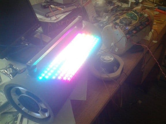
It didn’t take long for us to knock out some light patterns, the first problem being how to switch between them. That was solved with a potentiometer hooked to another AD converter input the result being used to switch the code between effects. There where some backlit led's in the speakers which seemed to respond very nicely to PWM based the music channels ADC value. It was suggested we add a white only mode as a room light, this morphed into several other colours in the blink of an eye. Orion came up with an ADC values sparkles of colour which looked great. He wanted to get the “band hero” look but it didn't quite happen, we got a river of modulated colour which looked nice ish. I tried the FFT thing but didn't spend enough time to get it working right. We tried rotating patterns at various speeds based on the music and many other variations. Some things worked well and some didn’t but we where having way to much fun each night to notice that due date was fast approaching.
Anyhow the hand in date for this school project came all to soon, so we never finished all that we set out to try in the software. The teachers were not impressed with it, which was very sad. They didn't understand the ardunio bit it even though Orion tried to explain it to them out of their own class textbook. Grades aside, we both had a ball building this hugely heavy (13kg) boom box which runs for many hours on a single charge. So if your wondering how to reconnect with your youth in more ways than one then build a arduino project with your kids and share the joy.


_ztBMuBhMHo.jpg?auto=compress%2Cformat&w=48&h=48&fit=fill&bg=ffffff)


Comments