

Hardware components | ||||||
 |
| × | 1 | |||
 |
| × | 1 | |||
 |
| × | 1 | |||
Software apps and online services | ||||||
 |
| |||||
| ||||||
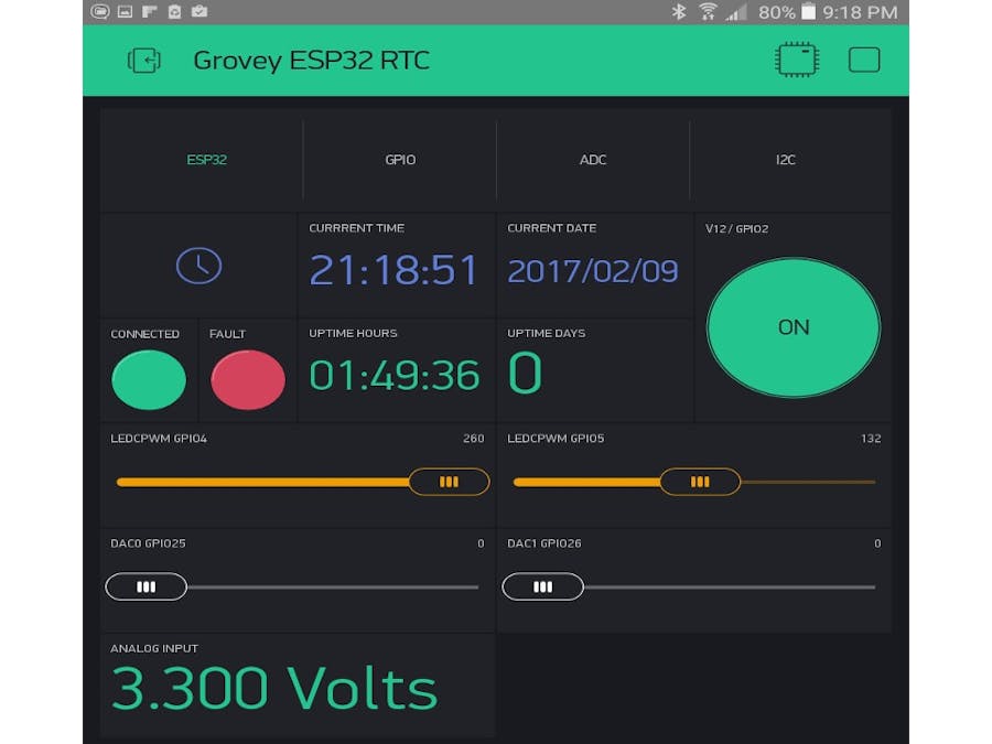
This project is a template for you to control your projects using the ESP32/ESP8266 and the Blynk IoT Graphical User Interface (GUI). It shows how to access the current server time and gives you graphical widgets to control your hardware.
DetailsUse this QRcode to replicate the Blynk GUI Interface:
Note Bene : This uses more resources than a "free" Blynk account and will require a paid subscription.
Grovey ESP32 WiFi RTC GPIO Sketch Overview
Overview of the "Virtual Pins" Used :
Grovey ESP32 Main Board :
- V0 - Reserved for Debugging messages
- V1 - Current Real-Time
- V2 - Current Date
- V3 - Hardware Uptime in Hour/Min/Sec
- V4 - Hardware Uptime in Days
- V5 - "Connected" Virtual LED
- V6 - "Fault" Virtual LED
- V7 - ADC Channel Reading (Battery Voltage) (Not working yet on ESP32)
- V8 - "ledc" channel 1 (ESP32 PWM) (thingSoC/Mikrobus PWM physical pin)
- V9 - "ledc" channel 2 (ESP32 PWM) Onboard Physical (yellow) LED
- V10 - sigmaDelta Digital to Analog (DAC) Channel 0
- V11 - sigmaDelta Digital to Analog (DAC) Channel 1
- V12 - Mapped to physical GPIO Pin 2
- V13 through V15 (not implemented yet)
Grovey GPIO Expansion Board :
- V16 Grovey GPIO Jack J1 Signal A - PWM Output
- V17 Grovey GPIO Jack J1 Signal B - Digital Input
- V18 Grovey GPIO Jack J1 Power - Digital Output
- V19 Grovey GPIO Jack J1 BLUE LED - PWM Output
- V20 Grovey GPIO Jack J2 Signal A - PWM Output
- V21 Grovey GPIO Jack J2 Signal B - Digital Input
- V22 Grovey GPIO Jack J12 Power - Digital Output
- V23 Grovey GPIO Jack J12 RED LED - PWM Output
- V24 Grovey GPIO Jack J3 Signal A - PWM Output
- V25 Grovey GPIO Jack J3 Signal B - Digital Input
- V26 Grovey GPIO Jack J3 Power - Digital Output
- V27 Grovey GPIO Jack J3 GREEN LED - PWM Output
- V28 Grovey GPIO Jack J4 Signal A - PWM Output
- V29 Grovey GPIO Jack J4 Signal B - Digital Input
- V30 Grovey GPIO Jack J4 Power - Digital Output
- V31 Grovey GPIO Jack J4 YELLOW LED - PWM Output
Grovey ADC Expansion Board :
- V32 Grovey ADC Jack J1 - Analog 16 bit ADC Input (5V)
- V33 Grovey ADC Jack J2 - Analog 16 bit ADC Input (5V)
- V34 Grovey ADC Jack J3 - Analog 16 bit ADC Input (5V)
- V35 Grovey ADC Jack J4 - Analog 16 bit ADC Input (5V)
Grovey I2C HUB Expansion Board :
V36 Grovey I2C Hub - Channel Selection (1 of 4 I2C switch channels)
The Grovey I2C HUB is a four port I2C switch with 3.3 Vole to 5.0 Volt level translation options. This allows you to add several peripherals with the same I2C address, on different ports. This is useful if you need to support several identical displays (LCD/OLED/etc.) or sensors such as temperature sensors, etc.
Note Bene : This project is a work in progress and will update frequently over the next several weeks, as the ESP32 Arduino Port and Blynk Ports are improved and updated.
Tom
If you find this project useful, please consider supporting our Crowd Funding campaign at: http://bit.ly/2kkKddJ
We could really use your help and support - thanks!
Install/Build instructionsStep 1
Installing the ESP32 CoreEspressif’s official ESP32 Arduino core is hosted here on GitHub. They don’t have an Arduino board manager install yet (it should be coming soon), but they do have a simple set of installation directions to help.
Step 2
Download the Blynk App for Android/IoS
Step 3
Install the Blynk Library for Arduino
Note: this must be done with the latest .zip file for Blynk 0.4.4 (or later) for the Server time function to work correctly! Note: If you get a date of 1/1/1970 then you are either a time-traveler, or using an older version of the Blynk library!
Step 4
Use the QRCode to get the screen layout
Step 5
Download and Install the Blynk_ESP32_WiFi_Grovey_ADC_GPIO.ino Sketch
Step 6
Compile and Upload the Blynk_ESP32_WiFi_Grovey_ADC_GPIO.ino Sketch
Step 7
Reset the ESP32 processor and watch it connect in the serial monitor
Step 8
Run the Blynk GUI on your phone or table and control your hardware!
/*************************************************************
 thingSoC Grovey ESP32 Wi-Fi embeddable module

 "thingSoC is a low-cost, highly-flexible and vendor agnostic
 socket system for IoT product development. It consists of both
 open-source hardware and software supporting many different
 processor types and integrated development environments."

 "The thingSoC "Grovey Series" was designed as "Everyday Electronics",
 a no-frills, low cost, approach to modular embedded product design.
 thingSoC boards are similar in size to most break-out-boards (BOBs),
 but feature a standardized stacking pinout, as well as a metadata
 keystore (Embedis) to indicate what peripherals are installed,
 and other project configutation settings."

    Downloads, docs, tutorials: http://thingsoc.github.io
    Social networks:            @PatternAgents

 The thingSoC hardware system is licensed under Creative Commons 4.0
 This code and the Embedis firmware library is licensed under MIT license

 This example code is in the public domain.
 *************************************************************
  Blynk is a platform with iOS and Android apps to control
  Arduino, Raspberry Pi and the likes over the Internet.
  You can easily build graphic interfaces for all your
  projects by simply dragging and dropping widgets.
    Downloads, docs, tutorials: http://www.blynk.cc
    Blynk community:            http://community.blynk.cc
    Social networks:            http://www.fb.com/blynkapp
                                http://twitter.com/blynk_app
  Blynk library is licensed under MIT license
  This example code is in public domain.
 *************************************************************
  Blynk can provide your device with time data, like an RTC.
  Please note that the accuracy of this method is up to several seconds.
  App project setup:
    RTC widget (no pin required)
    Value Display M widget on V1
    Value Display M widget on V2
  WARNING :
  For this example you'll need SimpleTimer library:
    https://github.com/jfturcot/SimpleTimer
  And also this Time keeping library:
    https://github.com/PaulStoffregen/Time
  This code is based on an example from the Time library:
    https://github.com/PaulStoffregen/Time/blob/master/examples/TimeSerial/TimeSerial.ino
 *************************************************************
 Grovey ESP32 WiFi RTC GPIO Sketch Overview

 Virtual Pins Used :
 V0  - Reserved for Debugging messages
 V1  - Current Real-Time
 V2  - Current Date
 V3  - Hardware Uptime in Hour/Min/Sec
 V4  - Hardware Uptime in Days
 V5  - "Connected" Virtual LED
 V6  - "Fault" Virtual LED
 V7  - ADC Channel Reading (Battery Voltage) (Not working yet on ESP32)
 V8  - "ledc" channel 1 (ESP32 PWM) (thingSoC/Mikrobus PWM physical pin)
 V9  - "ledc" channel 2 (ESP32 PWM) Onboard Physical (yellow) LED
 V10 - // sigmaDelta Digital to Analog (DAC) Channel 0
 V11 - // sigmaDelta Digital to Analog (DAC) Channel 1
 V12 - Mapped to physical GPIO Pin 2
 V13 - Available
 V14 - Available
 V15 - Available
 V16 - Grovey GPIO Jack J1 Signal A - PWM Output
 V17 - Grovey GPIO Jack J1 Signal B - Digital Input
 V18 - Grovey GPIO Jack J1 Power - Digital Output
 V19 - Grovey GPIO Jack J1 BLUE LED - PWM Output
 V20 - Grovey GPIO Jack J2 Signal A - PWM Output
 V21 - Grovey GPIO Jack J2 Signal B - Digital Input
 V22 - Grovey GPIO Jack J12 Power - Digital Output
 V23 - Grovey GPIO Jack J12 RED LED - PWM Output
 V24 - Grovey GPIO Jack J3 Signal A - PWM Output
 V25 - Grovey GPIO Jack J3 Signal B - Digital Input
 V26 - Grovey GPIO Jack J3 Power - Digital Output
 V27 - Grovey GPIO Jack J3 GREEN LED - PWM Output
 V28 - Grovey GPIO Jack J4 Signal A - PWM Output
 V29 - Grovey GPIO Jack J4 Signal B - Digital Input
 V30 - Grovey GPIO Jack J4 Power - Digital Output
 V31 - Grovey GPIO Jack J4 YELLOW LED - PWM Output

 *************************************************************/

/* Grovey ESP32 Blynk WiFi defines */
#define BLYNK_PRINT Serial    // Comment this out to disable prints and save space
#define DEBUG_FLAG 0
#include <WiFi.h>
#include <WiFiClient.h>
#include <BlynkSimpleEsp32.h>
#include <SimpleTimer.h>
#include <TimeLib.h>
#include <WidgetRTC.h>

/* Grovey GPIO Board (Semtech SX1509 GPIO chip) */
#include <Wire.h>
#include <SparkFunSX1509.h> // Include SX1509 library
/* SX1509 I2C address (set by ADDR1 and ADDR0 (00 by default): */
  const byte SX1509_ADDRESS = 0x3E;  // SX1509 I2C address 00
//const byte SX1509_ADDRESS = 0x3F;  // SX1509 I2C address 01
//const byte SX1509_ADDRESS = 0x70;  // SX1509 I2C address 02
//const byte SX1509_ADDRESS = 0x71;  // SX1509 I2C address 03
SX1509 io; // Instantiate the SX1509

// You should get Auth Token in the Blynk App.
// Go to the Project Settings (nut icon).
char auth[] = "XXXXXXXXXXXXXXXXXXXXXXXXXXXXXXXX";

// Your WiFi credentials.
// Set password to "" for open networks.
// Set security method to "WLAN_SEC_WPA2" if applicable
char ssid[] = "skynet";
char pass[] = "XXXXX";

// A timer instance to avoid flooding the Blynk Server
SimpleTimer timer;
// An RTC instance to obtain the real time from the Blynk Server
WidgetRTC rtc;
// A "virtual LED" instance to indicate connection state on pin V5
WidgetLED LED_connected(V5);
// A "virtual LED" instance to indicate the hardware state on pin V6
WidgetLED LED_fault(V6);

// LED widgets for Grovey GPIO input pins
WidgetLED GPIO_Led1(17);
WidgetLED GPIO_Led2(21);
WidgetLED GPIO_Led3(25);
WidgetLED GPIO_Led4(29);

/* Global variables for the Uptime calculation */
long Days_up    = 0;
int  Hours_up   = 0;
int  Minutes_up = 0;
int  Seconds_up = 0;
int  HighMillis = 0;
int  Rollover   =0;

/* calculate the hardware uptime based on the millis counter */
void uptime(){
  /* Note an expected rollover if the millis counter */
  if (millis()>=3000000000){
    HighMillis=1;
  }
  /* Flag the actual rollover of the millis counter */
  if (millis()<=100000&&HighMillis==1){
    Rollover++;
    HighMillis=0;
  }
  long secsUp = millis()/1000;
  Seconds_up = secsUp%60;
  Minutes_up = (secsUp/60)%60;
  Hours_up   = (secsUp/(60*60))%24;
  //First portion takes care of a rollover [around 50 days]
  Days_up    = (Rollover*50)+(secsUp/(60*60*24));
};

// Digital clock display of the current time
// The time is obtained from the Blynk server using the WidgetRTC
// and then "echoed" back to the server using pins V1 (time) and V2 (Date)
void clockDisplay()
{
  // You can call hour(), minute(), ... at any time
  // Please see Time library examples for details
  char currentDate[16];
  char currentTime[16];
  char upDays[16];
  char upHours[16];
  sprintf(currentDate, "%04d/%02d/%02d", year(), month(), day());
  sprintf(currentTime, "%02d:%02d:%02d", hour(), minute(), second());
  // Send time to the App
  Blynk.virtualWrite(V1, currentTime);
  // Send date to the App
  Blynk.virtualWrite(V2, currentDate);
  uptime();
  sprintf(upDays, "%06d", Days_up);
  sprintf(upHours, "%02d:%02d:%02d", Hours_up, Minutes_up, Seconds_up);
  // Send uptime to the App
  Blynk.virtualWrite(V3, upHours);
  Blynk.virtualWrite(V4, upDays);

  // Note Bene : AnalogRead seems to crash WiFi - don't use right now...
  //ADC0 = GPIO36 = TSOC IO1
  // float ana = (analogRead(A0) / 4096) * 3.3 ;
  //ADC19 = GPIO26 = TSOC IRQ
  // int ana = analogRead(A19); // Not Working Yet...
  float ana = 3.3;
  Blynk.virtualWrite(V7, ana);
}

void readGPIOinputs() {
  // J1
  if (io.digitalRead(1)) {
    GPIO_Led1.on();
  } else {
    GPIO_Led1.off();
  }
  // J2
  if (io.digitalRead(5)) {
    GPIO_Led2.on();
  } else {
    GPIO_Led2.off();
  }
  // J3
  if (io.digitalRead(9)) {
    GPIO_Led3.on();
  } else {
    GPIO_Led3.off();
  }
  // J4
  if (io.digitalRead(13)) {
    GPIO_Led4.on();
  } else {
    GPIO_Led4.off();
  }
}

// "ledc" channel 1 (ESP32 PWM)
// test "fault" LED to indicate out of range values
BLYNK_WRITE(V8) {
  int pinData = param.asInt();
  ledcWrite(1, pinData);
  // we're using ledC in eight (8) bit mode
  // so use "fault" to indiacte an out-of-bounds parameter
  // this is just an arbitrary example usage...
  if (pinData > 255) {
    LED_fault.on();
  } else {
    LED_fault.off();
  }
}

// "ledc" channel 2 (ESP32 PWM) Onboard Physical (yellow) LED
BLYNK_WRITE(V9) {
  int pinData = param.asInt();
  ledcWrite(2, pinData);
}

// sigmaDelta Digital to Analog (DAC) Channel 0
BLYNK_WRITE(V10) {
  int pinData = param.asInt();
  sigmaDeltaWrite(0, pinData);
}

// sigmaDelta Digital to Analog (DAC) Channel 1
BLYNK_WRITE(V11) {
  int pinData = param.asInt();
  sigmaDeltaWrite(1, pinData);
}

// Virtual pin 12 mapped to GPIO2 physical pin
// Yes, while this can be done directly to hardware pins
// in Blynk - it makes hardware changes easier to implement
// without changing/editing your Blynk GUI layout -
// this is an (arbitrary) example of how to do that...
BLYNK_WRITE(V12) {
  int pinData = param.asInt();
  if (pinData == 0) {
    digitalWrite(2, LOW);
  } else {
    digitalWrite(2, HIGH);
  }
}

BLYNK_WRITE(V16) {
  byte bright;
  int pinData = param.asInt();
  bright = 255 - (byte) pinData;
  io.analogWrite(0, bright);
}

BLYNK_WRITE(V18) {
  int pinData = param.asInt();
  if (pinData == 0) {
    io.digitalWrite(2, LOW);
  } else {
    io.digitalWrite(2, HIGH);
  }
}

BLYNK_WRITE(V19) {
  byte bright;
  int pinData = param.asInt();
  bright = 255 - (byte) pinData;
  io.analogWrite(3, bright);
}

BLYNK_WRITE(V20) {
  byte bright;
  int pinData = param.asInt();
  bright = 255 - (byte) pinData;
  io.analogWrite(4, bright);
}

BLYNK_WRITE(V22) {
  int pinData = param.asInt();
  if (pinData == 0) {
    io.digitalWrite(6, LOW);
  } else {
    io.digitalWrite(6, HIGH);
  }
}
BLYNK_WRITE(V23) {
  byte bright;
  int pinData = param.asInt();
  bright = 255 - (byte) pinData;
  io.analogWrite(7, bright);
}

BLYNK_WRITE(V24) {
  byte bright;
  int pinData = param.asInt();
  bright = 255 - (byte) pinData;
  io.analogWrite(8, bright);
}

BLYNK_WRITE(V26) {
  int pinData = param.asInt();
  if (pinData == 0) {
    io.digitalWrite(10, LOW);
  } else {
    io.digitalWrite(10, HIGH);
  }
}

BLYNK_WRITE(V27) {
  byte bright;
  int pinData = param.asInt();
  bright = 255 - (byte) pinData;
  io.analogWrite(11, bright);
}

BLYNK_WRITE(V28) {
  byte bright;
  int pinData = param.asInt();
  bright = 255 - (byte) pinData;
  io.analogWrite(12, bright);
}

BLYNK_WRITE(V30) {
  int pinData = param.asInt();
  if (pinData == 0) {
    io.digitalWrite(14, LOW);
  } else {
    io.digitalWrite(14, HIGH);
  }
}

BLYNK_WRITE(V31) {
  byte bright;
  int pinData = param.asInt();
  bright = 255 - (byte) pinData;
  io.analogWrite(15, bright);
}

void setup()
{
  // Debug console : note the the Arduino IDE default is 115200 baud
  // Change it if your requirements are different...
  Serial.begin(115200);
  Serial.println("Starting Grovey GPIO Board ... ");
  // Initialize the SX1509, returns "1" when successful, "0" if not.
  if (io.begin(SX1509_ADDRESS, 255)==0) {
    // If we fail to initialize the SX1509 chip,
    // then loop forever, slow blinking the built-in LED on the CPU board
    while (1) {
      delay(1000);
    }
  }
  /* Initialize the pinModes of the Grovey GPIO Board */
  io.pinMode(0,  ANALOG_OUTPUT);
  io.pinMode(1,  INPUT);
  io.pinMode(2,  OUTPUT);
  io.pinMode(3,  ANALOG_OUTPUT);
  io.pinMode(4,  ANALOG_OUTPUT);
  io.pinMode(5,  INPUT);
  io.pinMode(6,  OUTPUT);
  io.pinMode(7,  ANALOG_OUTPUT);
  io.pinMode(8,  ANALOG_OUTPUT);
  io.pinMode(9,  INPUT);
  io.pinMode(10, OUTPUT);
  io.pinMode(11, ANALOG_OUTPUT);
  io.pinMode(12, ANALOG_OUTPUT);
  io.pinMode(13, INPUT);
  io.pinMode(14, OUTPUT);
  io.pinMode(15, ANALOG_OUTPUT);
  Serial.println("Grovey GPIO Board Running... ");

  Serial.println("Starting Blynk... ");
  Blynk.begin(auth, ssid, pass);
  // use this is you need WPA2
  //Blynk.begin(auth, ssid, pass, security);

  Serial.println("Blynk Running... ");
  while(Blynk.connect() == false);      // wait for Blynk to connect to Server
  LED_connected.on();                   // catch-22 ?how to indicate disconnected?
  LED_fault.off();                      // same with fault?
  Serial.println("Blynk Connected... ");

  // Begin synchronizing time
  rtc.begin();
  Blynk.syncAll();

  // Other Time library functions can be used, like:
  //   timeStatus(), setSyncInterval(interval)...
  // Read more: http://www.pjrc.com/teensy/td_libs_Time.html

  // Display digital clock every 1 second
  // we do this to avoid flooding the Blynk server with too much data
  timer.setInterval(1000L, clockDisplay);

  // read the GPIO inputs once per second also
  // (sluggish , but this can be tuned... )
  timer.setInterval(1000L, readGPIOinputs);

  /* setup ESP32 pin modes */
  /* Setup two DAC channels GPIO25=ADC18, GPIO26=ADC19 */
  /* setup channel 0 with frequency 312500 Hz */
  sigmaDeltaSetup(0, 312500);
  //attach pin ADC18/GPIO25 to channel 0
  sigmaDeltaAttachPin(18,0);
  //initialize channel 0 to off
  sigmaDeltaWrite(0, 0);
  //setup channel 1 with frequency 312500 Hz
  sigmaDeltaSetup(1, 312500);
  //attach pin ADC19/GPIO26 to channel 1
  sigmaDeltaAttachPin(19,1);
  //initialize channel 1 to off
  sigmaDeltaWrite(1, 0);

  // Setup "ledC" PWM channel on GPIO4 & GPIO5
  ledcSetup(1, 50, 8); // channel 1, 50 Hz, 8-bit depth
  ledcAttachPin(4, 1);   // GPIO 4 on channel 1
  // N.B. GPIO5 is also SPI SS - comment the next two lines out if using SPI!
  ledcSetup(2, 50, 8); // channel 2, 50 Hz, 8-bit depth
  ledcAttachPin(5, 2);  // GPIO 5 on channel 2

  /* Setup digital/GPIO output on GPIO2 physical pin */
  pinMode( 2,   OUTPUT);
  /* Note Bene : AnalogRead seems to crash WiFi - don't use right now on ESP32 2/9/2017 */
  // pinMode( A0,  ANALOG);
  // pinMode( A19, ANALOG);
}

/* gotta love a "clean" main loop! */
void loop()
{
  Blynk.run();
  timer.run();
}

/* end of ESP32_WiFi_RTC.ino */
/*************************************************************
 thingSoC Grovey ESP32 Wi-Fi embeddable module

 "thingSoC is a low-cost, highly-flexible and vendor agnostic
 socket system for IoT product development. It consists of both
 open-source hardware and software supporting many different
 processor types and integrated development environments."

 "The thingSoC "Grovey Series" was designed as "Everyday Electronics",
 a no-frills, low cost, approach to modular embedded product design.
 thingSoC boards are similar in size to most break-out-boards (BOBs),
 but feature a standardized stacking pinout, as well as a metadata
 keystore (Embedis) to indicate what peripherals are installed,
 and other project configutation settings."

    Downloads, docs, tutorials: http://thingsoc.github.io
    Social networks:            @PatternAgents

 The thingSoC hardware system is licensed under Creative Commons 4.0
 This code and the Embedis firmware library is licensed under MIT license

 This example code is in the public domain.
 *************************************************************
  Blynk is a platform with iOS and Android apps to control
  Arduino, Raspberry Pi and the likes over the Internet.
  You can easily build graphic interfaces for all your
  projects by simply dragging and dropping widgets.
    Downloads, docs, tutorials: http://www.blynk.cc
    Blynk community:            http://community.blynk.cc
    Social networks:            http://www.fb.com/blynkapp
                                http://twitter.com/blynk_app

  Blynk can provide your device with time data, like an RTC.
  Please note that the accuracy of this method is up to several seconds.
  App project setup:
    RTC widget (no pin required)
    Value Display M widget on V1
    Value Display M widget on V2

  Blynk library is licensed under MIT license
  This example code is in public domain.
 *************************************************************
  Additional Libraires Required for this example
  Use the Sketch->Include Library->Library Manager to install
  or simply unzip the libraries into your Arduino->libraries directory

  SimpleTimer Library:
    https://github.com/jfturcot/SimpleTimer
  Time keeping Library:
    https://github.com/PaulStoffregen/Time

 ------------------------------------------------------------
  Additonal Libraries required for supporting the Grovey GPIO
  SX1509 GPIO Library:
  https://github.com/sparkfun/SparkFun_SX1509_Arduino_Library

 ------------------------------------------------------------
  Additonal Libraries required for supporting the Grovey ADC
  ADS1115/ADS1015 ADC Library:
  https://github.com/adafruit/Adafruit_ADS1X15

 *************************************************************
 Grovey ESP32 WiFi RTC GPIO Sketch Overview

 Virtual Pins Used :
 V0  - Reserved for Debugging messages
 V1  - Current Real-Time
 V2  - Current Date
 V3  - Hardware Uptime in Hour/Min/Sec
 V4  - Hardware Uptime in Days
 V5  - "Connected" Virtual LED
 V6  - "Fault" Virtual LED
 V7  - ADC Channel Reading (Battery Voltage) (Not working yet on ESP32)
 V8  - "ledc" channel 1 (ESP32 PWM) (thingSoC/Mikrobus PWM physical pin)
 V9  - "ledc" channel 2 (ESP32 PWM) Onboard Physical (yellow) LED
 V10 - // sigmaDelta Digital to Analog (DAC) Channel 0
 V11 - // sigmaDelta Digital to Analog (DAC) Channel 1
 V12 - Mapped to physical GPIO Pin 2
 V13 - Available
 V14 - Available
 V15 - Available
 ------------------------------------------------------------
 V16 - Grovey GPIO Jack J1 Signal A   - PWM Output
 V17 - Grovey GPIO Jack J1 Signal B   - Digital Input
 V18 - Grovey GPIO Jack J1 Power      - Digital Output
 V19 - Grovey GPIO Jack J1 BLUE LED   - PWM Output
 V20 - Grovey GPIO Jack J2 Signal A   - PWM Output
 V21 - Grovey GPIO Jack J2 Signal B   - Digital Input
 V22 - Grovey GPIO Jack J12 Power     - Digital Output
 V23 - Grovey GPIO Jack J12 RED LED   - PWM Output
 V24 - Grovey GPIO Jack J3 Signal A   - PWM Output
 V25 - Grovey GPIO Jack J3 Signal B   - Digital Input
 V26 - Grovey GPIO Jack J3 Power      - Digital Output
 V27 - Grovey GPIO Jack J3 GREEN LED  - PWM Output
 V28 - Grovey GPIO Jack J4 Signal A   - PWM Output
 V29 - Grovey GPIO Jack J4 Signal B   - Digital Input
 V30 - Grovey GPIO Jack J4 Power      - Digital Output
 V31 - Grovey GPIO Jack J4 YELLOW LED - PWM Output
 ------------------------------------------------------------
 V32 - Grovey ADC Jack J1 (Analog Input)
 V33 - Grovey ADC Jack J1 (Analog Input)
 V34 - Grovey ADC Jack J1 (Analog Input)
 V35 - Grovey ADC Jack J1 (Analog Input)
 ------------------------------------------------------------

 *************************************************************/

/* Grovey ESP32 Blynk WiFi defines */
#define BLYNK_PRINT Serial    // Comment this out to disable prints and save space
#define DEBUG_FLAG 0
#include <WiFi.h>
#include <WiFiClient.h>
#include <BlynkSimpleEsp32.h>
#include <SimpleTimer.h>
#include <TimeLib.h>
#include <WidgetRTC.h>

/* Grovey GPIO Board (Semtech SX1509 GPIO chip) */
#include <Wire.h>
#include <SparkFunSX1509.h> // Include SX1509 library
/* SX1509 I2C address (set by ADDR1 and ADDR0 (00 by default): */
  const byte SX1509_ADDRESS = 0x3E;  // SX1509 I2C address 00
//const byte SX1509_ADDRESS = 0x3F;  // SX1509 I2C address 01
//const byte SX1509_ADDRESS = 0x70;  // SX1509 I2C address 02
//const byte SX1509_ADDRESS = 0x71;  // SX1509 I2C address 03
SX1509 io; // Instantiate the SX1509

/* Library for the Grovey ADC board */
#include <Adafruit_ADS1015.h>
// Adafruit_ADS1115 ads;  /* Use this for the 16-bit version */
Adafruit_ADS1015 ads;     /* Use this for the 12-bit version */

// You should get Auth Token in the Blynk App.
// Go to the Project Settings (nut icon).
char auth[] = "XXXXXXXXXXXXXXXXXXXXXXXXXXXXXXXX";

// Your WiFi credentials.
// Set password to "" for open networks.
// Set security method to "WLAN_SEC_WPA2" if applicable
char ssid[] = "skynet";
char pass[] = "XXXXX";

// A timer instance to avoid flooding the Blynk Server
SimpleTimer timer;
// An RTC instance to obtain the real time from the Blynk Server
WidgetRTC rtc;
// A "virtual LED" instance to indicate connection state on pin V5
WidgetLED LED_connected(V5);
// A "virtual LED" instance to indicate the hardware state on pin V6
int fault, fault_last = 0;
WidgetLED LED_fault(V6);

// LED widgets for Grovey GPIO input pins
byte LED1_state, LED2_state, LED3_state, LED4_state = 0;
WidgetLED GPIO_Led1(17);
WidgetLED GPIO_Led2(21);
WidgetLED GPIO_Led3(25);
WidgetLED GPIO_Led4(29);

/* Global variables for the Uptime calculation */
long Days_up    = 0;
int  Hours_up   = 0;
int  Minutes_up = 0;
int  Seconds_up = 0;
int  HighMillis = 0;
int  Rollover   =0;

/* calculate the hardware uptime based on the millis counter */
void uptime(){
  /* Note an expected rollover if the millis counter */
  if (millis()>=3000000000){
    HighMillis=1;
  }
  /* Flag the actual rollover of the millis counter */
  if (millis()<=100000&&HighMillis==1){
    Rollover++;
    HighMillis=0;
  }
  long secsUp = millis()/1000;
  Seconds_up = secsUp%60;
  Minutes_up = (secsUp/60)%60;
  Hours_up   = (secsUp/(60*60))%24;
  //First portion takes care of a rollover [around 50 days]
  Days_up    = (Rollover*50)+(secsUp/(60*60*24));
};

// Digital clock display of the current time
// The time is obtained from the Blynk server using the WidgetRTC
// and then "echoed" back to the server using pins V1 (time) and V2 (Date)
void clockDisplay()
{
  // You can call hour(), minute(), ... at any time
  // Please see Time library examples for details
  char currentDate[16];
  char currentTime[16];
  char upDays[16];
  char upHours[16];
  sprintf(currentDate, "%04d/%02d/%02d", year(), month(), day());
  sprintf(currentTime, "%02d:%02d:%02d", hour(), minute(), second());
  // Send time to the App
  Blynk.virtualWrite(V1, currentTime);
  // Send date to the App
  Blynk.virtualWrite(V2, currentDate);
  uptime();
  sprintf(upDays, "%06d", Days_up);
  sprintf(upHours, "%02d:%02d:%02d", Hours_up, Minutes_up, Seconds_up);
  // Send uptime to the App
  Blynk.virtualWrite(V3, upHours);
  Blynk.virtualWrite(V4, upDays);

  // Note Bene : AnalogRead seems to crash WiFi - don't use right now...
  //ADC0 = GPIO36 = TSOC IO1
  // float ana = (analogRead(A0) / 4096) * 3.3 ;
  //ADC19 = GPIO26 = TSOC IRQ
  // int ana = analogRead(A19); // Not Working Yet...
  //float ana = 3.3;
  //Blynk.virtualWrite(V7, "3.30");

  // in order not to flood the blynk server, only update if changed
  // J1
  if ( io.digitalRead(1) != LED1_state) {
    LED1_state = io.digitalRead(1);
    if (LED1_state) {
      GPIO_Led1.on();
    } else {
      GPIO_Led1.off();
    }
  }
  if ( io.digitalRead(5) != LED2_state) {
    LED2_state = io.digitalRead(5);
    if (LED2_state) {
      GPIO_Led2.on();
    } else {
      GPIO_Led2.off();
    }
  }

  if ( io.digitalRead(9) != LED3_state) {
    LED3_state = io.digitalRead(9);
    if (LED3_state) {
      GPIO_Led3.on();
    } else {
      GPIO_Led3.off();
    }
  }
  if ( io.digitalRead(13) != LED4_state) {
    LED4_state = io.digitalRead(13);
    if (LED4_state) {
      GPIO_Led4.on();
    } else {
      GPIO_Led4.off();
    }
  }

  // You can't send any value at any time or you'll flood the Blynk Server
  // Please don't send more that 10 values per second.
  // So this is called from the SimpleTimer once per second
  int16_t adc0, adc1, adc2, adc3 = 0;                     // local variables to hold the current ADC readings
  int16_t adc0_last, adc1_last, adc2_last, adc3_last = 0; // local variables to hold the last ADC readings
  // Virtual Pin V32 is used to push the ADC0 reading
  adc0 = ads.readADC_SingleEnded(0);
  if (adc0 != adc0_last) {
    adc0_last = adc0;
    Blynk.virtualWrite(V32, adc0);
    //Serial.print("AIN1: "); Serial.println(adc0);
  }
  // Virtual Pin V33 is used to push the ADC1 reading
  adc1 = ads.readADC_SingleEnded(1);
  if (adc1 != adc1_last) {
    adc1_last = adc1;
    Blynk.virtualWrite(V33, adc1);
    //Serial.print("AIN2: "); Serial.println(adc1);
  }
  // Virtual Pin V34 is used to push the ADC2 reading
  adc2 = ads.readADC_SingleEnded(2);
  if (adc2 != adc2_last) {
    adc2_last = adc2;
    Blynk.virtualWrite(V34, adc2);
    //Serial.print("AIN3: "); Serial.println(adc3);
  }
  // Virtual Pin V35 is used to push the ADC3 reading
  adc3 = ads.readADC_SingleEnded(3);
  if (adc3 != adc3_last) {
    adc3_last = adc3;
    Blynk.virtualWrite(V35, adc3);
    //Serial.print("AIN4: "); Serial.println(adc3);
  }
}

// "ledc" channel 1 (ESP32 PWM)
// test "fault" LED to indicate out of range values
BLYNK_WRITE(V8) {
  int pinData = param.asInt();
  ledcWrite(1, pinData);
  // we're using ledC in eight (8) bit mode
  // so use "fault" to indiacte an out-of-bounds parameter
  // this is just an arbitrary example usage...
  if (pinData > 255) {
    fault = 1;
  } else {
    fault = 0;
  }

  // only send updates when value changes...
  if (fault_last != fault) {
     fault_last = fault;
     if (fault) {
       LED_fault.on();
     } else {
       LED_fault.off();
     }
  }
}

// "ledc" channel 2 (ESP32 PWM) Onboard Physical (yellow) LED
BLYNK_WRITE(V9) {
  int pinData = param.asInt();
  ledcWrite(2, pinData);
}

// sigmaDelta Digital to Analog (DAC) Channel 0
BLYNK_WRITE(V10) {
  int pinData = param.asInt();
  sigmaDeltaWrite(0, pinData);
}

// sigmaDelta Digital to Analog (DAC) Channel 1
BLYNK_WRITE(V11) {
  int pinData = param.asInt();
  sigmaDeltaWrite(1, pinData);
}

// Virtual pin 12 mapped to GPIO2 physical pin
// Yes, while this can be done directly to hardware pins
// in Blynk - it makes hardware changes easier to implement
// without changing/editing your Blynk GUI layout -
// this is an (arbitrary) example of how to do that...
BLYNK_WRITE(V12) {
  int pinData = param.asInt();
  if (pinData == 0) {
    digitalWrite(2, LOW);
  } else {
    digitalWrite(2, HIGH);
  }
}

BLYNK_WRITE(V16) {
  byte bright;
  int pinData = param.asInt();
  bright = 255 - (byte) pinData;
  io.analogWrite(0, bright);
}

BLYNK_WRITE(V18) {
  int pinData = param.asInt();
  if (pinData == 0) {
    io.digitalWrite(2, LOW);
  } else {
    io.digitalWrite(2, HIGH);
  }
}

BLYNK_WRITE(V19) {
  byte bright;
  int pinData = param.asInt();
  bright = 255 - (byte) pinData;
  io.analogWrite(3, bright);
}

BLYNK_WRITE(V20) {
  byte bright;
  int pinData = param.asInt();
  bright = 255 - (byte) pinData;
  io.analogWrite(4, bright);
}

BLYNK_WRITE(V22) {
  int pinData = param.asInt();
  if (pinData == 0) {
    io.digitalWrite(6, LOW);
  } else {
    io.digitalWrite(6, HIGH);
  }
}
BLYNK_WRITE(V23) {
  byte bright;
  int pinData = param.asInt();
  bright = 255 - (byte) pinData;
  io.analogWrite(7, bright);
}

BLYNK_WRITE(V24) {
  byte bright;
  int pinData = param.asInt();
  bright = 255 - (byte) pinData;
  io.analogWrite(8, bright);
}

BLYNK_WRITE(V26) {
  int pinData = param.asInt();
  if (pinData == 0) {
    io.digitalWrite(10, LOW);
  } else {
    io.digitalWrite(10, HIGH);
  }
}

BLYNK_WRITE(V27) {
  byte bright;
  int pinData = param.asInt();
  bright = 255 - (byte) pinData;
  io.analogWrite(11, bright);
}

BLYNK_WRITE(V28) {
  byte bright;
  int pinData = param.asInt();
  bright = 255 - (byte) pinData;
  io.analogWrite(12, bright);
}

BLYNK_WRITE(V30) {
  int pinData = param.asInt();
  if (pinData == 0) {
    io.digitalWrite(14, LOW);
  } else {
    io.digitalWrite(14, HIGH);
  }
}

BLYNK_WRITE(V31) {
  byte bright;
  int pinData = param.asInt();
  bright = 255 - (byte) pinData;
  io.analogWrite(15, bright);
}

void setup()
{
  // Debug console : note the the Arduino IDE default is 115200 baud
  // Change it if your requirements are different...
  Serial.begin(115200);
  Serial.println("Starting Grovey GPIO Board ... ");
  // Initialize the SX1509, returns "1" when successful, "0" if not.
  if (io.begin(SX1509_ADDRESS, 255)==0) {
    // If we fail to initialize the SX1509 chip,
    // then loop forever, slow blinking the built-in LED on the CPU board
    while (1) {
      delay(1000);
    }
  }
  /* Initialize the pinModes of the Grovey GPIO Board */
  io.pinMode(0,  ANALOG_OUTPUT);
  io.pinMode(1,  INPUT);
  io.pinMode(2,  OUTPUT);
  io.pinMode(3,  ANALOG_OUTPUT);
  io.pinMode(4,  ANALOG_OUTPUT);
  io.pinMode(5,  INPUT);
  io.pinMode(6,  OUTPUT);
  io.pinMode(7,  ANALOG_OUTPUT);
  io.pinMode(8,  ANALOG_OUTPUT);
  io.pinMode(9,  INPUT);
  io.pinMode(10, OUTPUT);
  io.pinMode(11, ANALOG_OUTPUT);
  io.pinMode(12, ANALOG_OUTPUT);
  io.pinMode(13, INPUT);
  io.pinMode(14, OUTPUT);
  io.pinMode(15, ANALOG_OUTPUT);
  Serial.println("Grovey GPIO Board Running... ");

  // The ADC input range (or gain) can be changed via the following
  // functions, but be careful never to exceed VDD +0.3V max, or to
  // exceed the upper and lower limits if you adjust the input range!
  // Setting these values incorrectly may destroy your ADC!
  //                                                                ADS1015  ADS1115
  //                                                                -------  -------
  ads.setGain(GAIN_TWOTHIRDS);  // 2/3x gain +/- 6.144V  1 bit = 3mV      0.1875mV (default)
  // ads.setGain(GAIN_ONE);        // 1x gain   +/- 4.096V  1 bit = 2mV      0.125mV
  // ads.setGain(GAIN_TWO);        // 2x gain   +/- 2.048V  1 bit = 1mV      0.0625mV
  // ads.setGain(GAIN_FOUR);       // 4x gain   +/- 1.024V  1 bit = 0.5mV    0.03125mV
  // ads.setGain(GAIN_EIGHT);      // 8x gain   +/- 0.512V  1 bit = 0.25mV   0.015625mV
  // ads.setGain(GAIN_SIXTEEN);    // 16x gain  +/- 0.256V  1 bit = 0.125mV  0.0078125mV
  Serial.println("Starting ADS ADC... ");
  ads.begin();
  Serial.println("Grovey ADC Board Running... ");

  Serial.println("Starting Blynk... ");
  Blynk.begin(auth, ssid, pass);
  // use this is you need WPA2
  //Blynk.begin(auth, ssid, pass, security);

  Serial.println("Blynk Running... ");
  while(Blynk.connect() == false);      // wait for Blynk to connect to Server
  Serial.println("Blynk Connected... ");

  // Begin synchronizing time
  rtc.begin();
  Blynk.syncAll();

  // Other Time library functions can be used, like:
  //   timeStatus(), setSyncInterval(interval)...
  // Read more: http://www.pjrc.com/teensy/td_libs_Time.html
  // Update Display digital clock every 1.5 seconds
  // we do this to avoid flooding the Blynk server with too much data
  timer.setInterval(1500L, clockDisplay);

  /* setup ESP32 pin modes */
  /* Setup two DAC channels GPIO25=ADC18, GPIO26=ADC19 */
  /* setup channel 0 with frequency 312500 Hz */
  sigmaDeltaSetup(0, 312500);
  //attach pin ADC18/GPIO25 to channel 0
  sigmaDeltaAttachPin(18,0);
  //initialize channel 0 to off
  sigmaDeltaWrite(0, 0);
  //setup channel 1 with frequency 312500 Hz
  sigmaDeltaSetup(1, 312500);
  //attach pin ADC19/GPIO26 to channel 1
  sigmaDeltaAttachPin(19,1);
  //initialize channel 1 to off
  sigmaDeltaWrite(1, 0);

  // Setup "ledC" PWM channel on GPIO4 & GPIO5
  ledcSetup(1, 50, 8); // channel 1, 50 Hz, 8-bit depth
  ledcAttachPin(4, 1);   // GPIO 4 on channel 1
  // N.B. GPIO5 is also SPI SS - comment the next two lines out if using SPI!
  ledcSetup(2, 50, 8); // channel 2, 50 Hz, 8-bit depth
  ledcAttachPin(5, 2);  // GPIO 5 on channel 2

  /* Setup digital/GPIO output on GPIO2 physical pin */
  pinMode( 2,   OUTPUT);
  /* Note Bene : AnalogRead seems to crash WiFi - don't use right now on ESP32 2/9/2017 */
  // pinMode( A0,  ANALOG);
  // pinMode( A19, ANALOG);

  // Since ADC Volt measurement not working yet on ESP32 , we'll do this once in setup...
  Blynk.virtualWrite(V7, "3.30");
  GPIO_Led1.off();
  GPIO_Led2.off();
  GPIO_Led3.off();
  GPIO_Led4.off();
  LED_fault.off();
  LED_connected.on();
}

/* gotta love a "clean" main loop! */
void loop()
{
  Blynk.run();
  timer.run();
}

/* end of ESP32_WiFi_RTC_GPIO_ADC.ino */


Comments