


Hardware components | ||||||
 |
| × | 1 | |||
 |
| × | 1 | |||
| × | 1 | ||||
The traditional way to read a resistance-based sensor - such as a force-sensitive resistor (FSR) - is to connect the sensor as one of the arms of a Wheatstone bridge. This approach is shown in the following figure. Here Rx is the unknown resistance, which can be calculated using the values of the other three resistors.
We ran into an issue with the conventional setup when we had to measure very precise resistance which varies in a few milli-ohms. The traditional did not work for us because:
1. The output voltage from the bridge would depend completely on the excitation voltage and the quality of the voltage source used. Even if a high-precision ADC is used, it still depends on the characteristics of the excitation voltage source.
2. The temperature variation in resistance of the three bridge resistors means that the thermal noise in them could skew the sensor readings.
3. High component count (take into account the bandgap reference used for excitation)
What we did:We wanted to use a constant current source for excitation of the sensor, rather than a voltage source. We used the TI's ADS1220 24-bit ADC (on a board from ProtoCentral) which is a 24-bit high-precision ADC with a low-noise front-end as well as built-in current source!
We immediately got to work trying to put together a setup to read the voltage using the ADC with a current source powering the resistor. This is a simple relation of Ohm's law (V=IR).
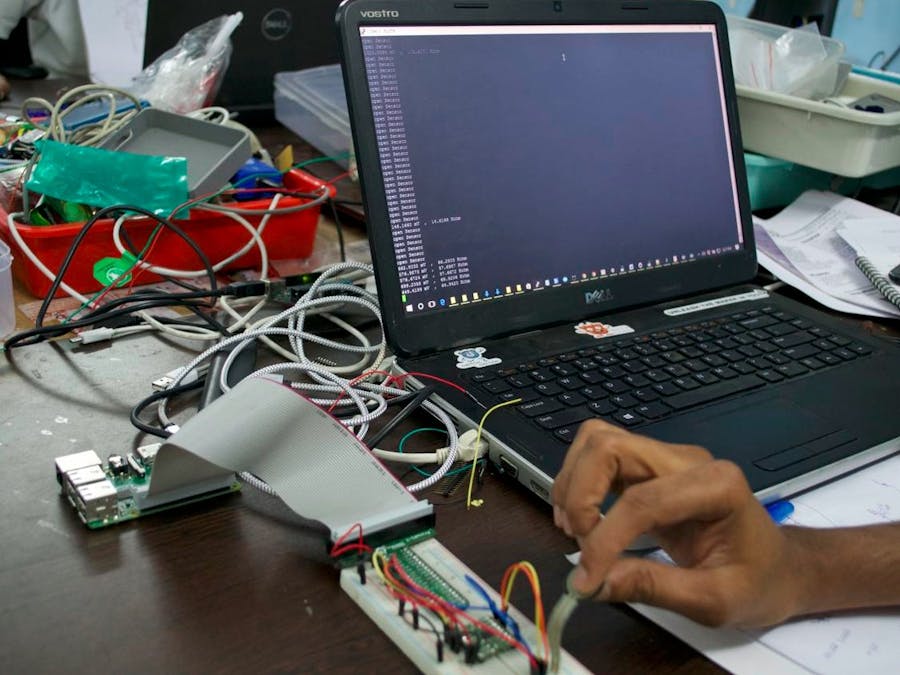
We used a Raspberry Pi to read the data using Python, using SPI to communicate with the ADS1220 breakout board. We used the ProtoCentral ProtoPi-T with USB access to control the Raspberry Pi without connecting to a monitor. Our setup looked something like this (apologies for bad photography):
In the software running on the Raspberry Pi, we have setup the ADS1220 to communicate with the Pi through SPI. The internal multiplexer on the chip is used to read the differential voltage drop across the sensor and two channels are routed internally for the current source output.
What we saw:We noticed that we were able to sense even very small changes in resistance. Here we have demonstrated using the FSR, but this was originally done for a medical pressure sensor. While for an FSR, a precision reading may not be required (for most applications), for an application actually requiring high precision, this approach worked out really well.
Setting up current sources and achieving precision current control can get complicated and also expensive, which explains the lack of projects using this technique for measurement. However, the ADS1220 simplifies all this by putting together everything on the same chip.
Check out the Python script below to try it out on your own.


Comments