To provide battery power to TI LaunchPads and enables their portability
×
1
BOOST-DRV8848
To drive a brushed DC motor
×
1
HS-311 Standard Servo
×
1
3-Speed Crank Axle Gearbox
×
1
LM339 Quad Comparator
×
1
Hand tools and fabrication machines
Soldering iron (generic)
Super Glue
Bandsaw
Story
Often times when it comes to using solar panels to power vehicles, a single solar panel or even an array of panels can result in wasted power. Thus, in order to achieve the desired power level, one would need to implement more panels. However, having a controller that can implement the Maximum Power Point Tracking (MPPT) algorithm allows for reduced cost of equipment while harvesting power in the most optimal manner.
There is a multitude of applications that an intelligent vehicle which implements MPPT has. Certain applications include charging batteries, running a solar PV power system, or even powering an electric motor. However, it is imperative to note that the load required by such systems can demand more power that the system can deliver. Thus, there is a need for maximizing the power from the system, which can be achieved by MPPT.
To be able to continuously observe where the maximum power is, we have implemented a perturb and observe (P&0) algorithm. This algorithm functions by observing the levels of voltage and current at different points and detecting the change in the power output. The direction of change is reversed when the power decreases. One potential downside to this algorithm is that if there sudden changes in sunlight, it can possibly result in choosing the wrong direction of search (in our case - forwards/backwards). While developing the algorithm, it was also important to consider the step size of the tracking. This is because too large of a step size will result in oscillation about the maximum power point, and too small will result in a poor response to changes in sunlight.
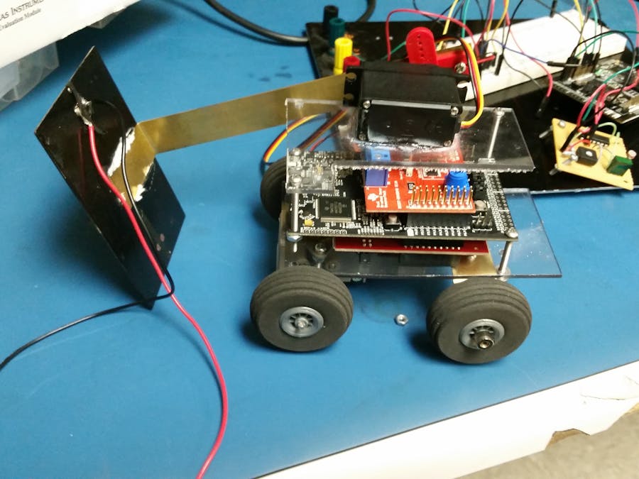
The majority of the vehicle construction was done at the Dallas Makerspace. The Makerspace has a wide variety of tools and work stations that can be used. Early stages of the vehicle build included cutting a sheet of Lexan Polycarbonate to the desired size and drilling holes. The idea was to have enough space to fit the LaunchPad and its associated booster packs, as well as having space for the analog front end. Shown below are a few pictures of the early stages of the build and parts used:
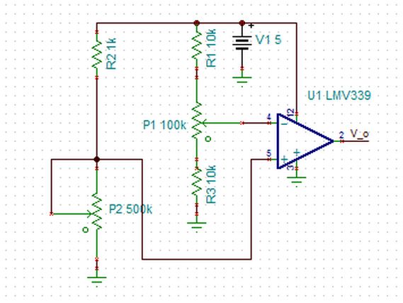
Comparator circuit that is essentially a light detection circuit. Functions as an analog interrupt block for the MPPT vehicle. Based on whether the vehicle detects light or not, it will move accordingly. Then we utilize the Perturb and Observe algorithm to optimize power output. (Designed in TINA-TI, a SPICE-based analog simulation program) The issue we ran into here was that the circuit ceased to function properly when we transferred it to a perforated prototyping board.
MPPT used to control a servo attached to a mast with a solar panel glued to the end of it. Duty cycles much quicker than its drive shaft counterpart.
// Servo library used to make panel tilt algorithm//this code wil track the maximum input power of the sun for a given angle//by way of Perturb and Observe (loosely based on the popular P&O algorithm)#include <Servo.h> Servomyservo;//create servo object to control a servo // a maximum of eight servo objects can be created intpos=0;// variable to store the servo position floatPdiff=0;doubleR=2000000;//resistance in ohms of the current sampling resistor (2Mohm)intpos_start=45;//dynamic value for the starting position of the servo controlling the panel anglevoidsetup(){Serial.begin(115200);//intiialize serial communication for printing values//debug basicallymyservo.attach(9);// attaches the servo on pin 9 to the servo object }voidloop(){//Initalize measurementsfloatVmeas=analogRead(2);//positive side panel voltage on pin2floatVmeas_I=analogRead(5);//negative side panel voltage reading (across 2.2 ohm resistor) on pin 5floatV_1=0;//might convert to int in the interest of saving memoryfloatI_1=0;floatP_1=0;floatV_2=0;floatI_2=0;floatP_2=0;floatVc=(3.3/1023);//voltage correction factor for the ADC (note: may be more than 10 bit ADC on 432)//=========================================================================================================================//Track in the positive direction....//=========================================================================================================================for(pos=pos_start;pos<135;pos+=1)// goes from a min of 45 degrees to max of 180 degrees //in steps of one degree{Vmeas=analogRead(2);//positive side panel voltage on pin2Vmeas_I=analogRead(5);//negative side panel voltage reading (across 2.2 ohm resistor) on pin 5V_1=2*Vmeas*Vc;//measure voltage at past time stampI_1=((Vmeas-Vmeas_I)*Vc)/R;//measure current at past time stampP_1=V_1*I_1;//calculate power myservo.write(pos);// tell servo to go to position in variable 'pos'// Perterb!!Serial.print("\n\nP_1\n");Serial.println(P_1);//optional, only to view the voltages we are gettingdelay(1000);// waits 50ms for the servo to reach the position Vmeas=analogRead(2);//positive side panel voltage on pin2Vmeas_I=analogRead(5);//negative side panel voltage reading (across 2.2 ohm resistor) on pin 5V_2=2*Vc*Vmeas;//Repeat all measurements again (Observe!!)I_2=((Vmeas-Vmeas_I)*Vc)/R;P_2=V_2*I_2;Serial.print("\n\nP_2\n");Pdiff=P_2-P_1;if(Pdiff<0)//if the power is dropping, go the other direction, if it is not dropping keep climbing the hill!{//Serial.println(Pdiff); //debug linepos_start=pos;//update the start position so that the controller does not move when entering the next loopbreak;//break into the next for loop}}pos_start=pos;//=============================================================================================================================//Track in the negative direction.... Constantly Updatting and tracking the maximum powerpoint//=============================================================================================================================for(pos=pos_start;pos>=45;pos-=1)// goes from a max of 180 degrees to min of 45 degrees //in steps of one degree{Vmeas=analogRead(2);//positive side panel voltage on pin2Vmeas_I=analogRead(5);//negative side panel voltage reading (across 2.2 ohm resistor) on pin 5V_1=2*Vc*Vmeas;//measure voltage at past time stampI_1=(Vmeas-Vmeas_I)/R;//measure current at past time stampP_1=V_1*I_1;//calculate power myservo.write(pos);// tell servo to go to position in variable 'pos'// (Perterb!!)//Serial.println(-(V_1)); //debug linedelay(1000);// waits 50ms for the servo to reach the position Vmeas=analogRead(2);//positive side panel voltage on pin2Vmeas_I=analogRead(5);//negative side panel voltage reading (across 2 Mohm resistor) on pin 5V_2=2*Vc*Vmeas;//Repeat all measurements again (Observe!!)I_2=(Vmeas-Vmeas_I)/R;P_2=V_2*I_2;Pdiff=P_2-P_1;//Serial.println(-(V_2)); //debug lineif(Pdiff<0)//if the power is dropping, go the other direction, if it is not dropping keep climbing the hill!{pos_start=pos;//update the start position so that the controller does not move when entering the next loopbreak;//break into the next for loop}}//=============================================================================================================================//Enter the postive direction loop again....//==============================================================================================================================pos_start=pos;//Serial.print("Loop Switch"); //debug line}
Drive Shaft Code
C/C++
MPPT driving the entire vehicle forwards and backwards to steer it away from obstacles that could inhibit sunlight.
// PWM control of the Brushed DC motor shaft//No libraries needed :)//note: code can probably be broken down into a couple of if statements in the void loop//we will perterb the motor very slowly (at least a hell of a lot slower than the angle of the panel)floatPdiffs=0;doubleRs=2000000;//resistance in ohms of the current sampling resistor (2Mohm)floatV_1s=0;//might convert to int in the interest of saving memoryfloatI_1s=0;floatP_1s=0;floatV_2s=0;floatI_2s=0;floatP_2s=0;floatVcs=(3.3/1023);//voltage correction factor for the ADC (note: may be more than 10 bit ADC on 432)voidsetup(){Serial.begin(115200);//intiialize serial communication for printing values }voidloop(){//the same measurements will need to be taken in parallel, think of the drive shaft as its own seperate subsytem running regardless of what the panel is doing//the shaft will have no memory of what the panel did in the preceding steps, rather, it will run on its own memory schema//Initalize measurementsfloatVmeass=analogRead(2);//positive side panel voltage on pin2floatVmeas_Is=analogRead(5);//negative side panel voltage reading (across 2.2 ohm resistor) on pin 5//perform calculationsV_2s=2*Vmeass*Vcs;//measure voltage at past time stampI_2s=((Vmeass-Vmeas_Is)*Vcs)/Rs;//measure current at past time stampP_2s=V_2s*I_2s;//calculate power //Serial.print("\n\nP_2s\n"); //debug lines//Serial.println(P_2s); //optional, only to view the voltages we are getting//=========================================================================================================================//Enter if statement to move the car appreciably in one direction or the other...//=========================================================================================================================//PWM section of code//==========================================================================================================================//note, cannot use the analogWrite function, have to resort to -bit banging-if(Pdiffs<0)// goes from a min of 45 degrees to max of 180 degrees //in steps of one degree{for(inti=0;i==10;i+=1){Serial.write("flag");digitalWrite(13,LOW);//H-Bridge commands for the DC motor (see truth table at bottom of code)// AIN1digitalWrite(12,HIGH);delay(25);digitalWrite(13,LOW);//AIN2digitalWrite(12,LOW);delay(75);//currently a 25% duty cycle with T = 100ms for a total PWM on-time of 1 second}}else{for(intj=0;j==10;j+=1){digitalWrite(13,HIGH);digitalWrite(12,LOW);delay(25);digitalWrite(13,LOW);digitalWrite(12,LOW);delay(75);}}digitalWrite(13,LOW);//stop the motor at next perturbation pointdigitalWrite(12,LOW);//========================================================================================================================================//take a new measurement at the next placeVmeass=analogRead(2);//positive side panel voltage on pin2Vmeas_Is=analogRead(5);//negative side panel voltage reading (across 2.2 ohm resistor) on pin 5V_1s=2*Vcs*Vmeass;//Repeat all measurements again (Observe!!)//note a voltage divider has been used to attenuate the voltage to a manageable level on pin 5I_1s=((Vmeass-Vmeas_Is)*Vcs)/Rs;P_1s=V_1s*I_1s;//Serial.print("\n\nP_1s\n"); //debug lines//Serial.print(P_1s);Pdiffs=P_2s-P_1s;//this is the Vdiff calculation that will determine the direction that the car movesdelay(100000);//extremely long delay added to ensure slow perturbation}


Comments