


Hardware components | ||||||
_ztBMuBhMHo.jpg?auto=compress%2Cformat&w=48&h=48&fit=fill&bg=ffffff) |
| × | 1 | |||
 |
| × | 1 | |||
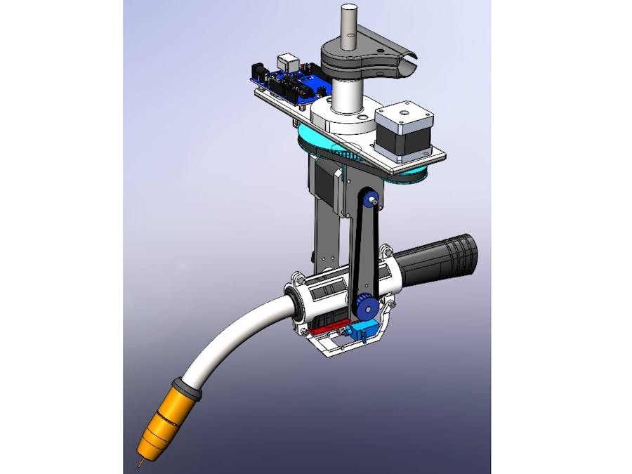
The scope of this project was to build a robotic adapter for a Millermatic 212 welding torch. The device adapted the welding torch to an ER32 collet holder for use in a CNC machine. The adapter was required to use an Arduino Uno and Adafruit motor shield. The project also required the usage of two stepper motors. One stepper motor provided the rotation of the torch around the CNC machine's spindle axis and the other provided the angle of attack for welding. Micro switches were required to provide feedback to the micro-controllers and define the home positions for the robot. Activation of the torch trigger was required by a servo. Some type of cable strain relief was required to control one meter of welding cable during the robot's sequence.
SequenceThe required sequence included:
- 1) starting at the home position;
- 2) depressing and holding the switch;
- 3) rotating down 45 degrees;
- 4) releasing the switch;
- 5) rotating up 45 degrees to return to horizontal;
- 6) depressing and holding the switch;
- 7) rotating 180 degrees about the spindle axis (clockwise, for example);
- 8) releasing the switch; and
- 9) rotating back 180 degrees (counterclockwise if the first direction was clockwise) to the original orientation (see Figure).
Following multiple conceptual ideas, a CAD model was generated for our final design. The final design incorporated ideas from all team members.
Following the calculations and FEA on each component, manufacturing and procurement began for the project. The additive manufactured components were sent to the 3D printing lab at UNCC. They were manufactured from ABS material.
The base plate components were manufactured from 6061-T6 aluminum and the spindle shaft was manufactured from low carbon steel. Machining for those components were done by the Team 2 members.
After all components were ready, the robot was assembled for testing. An additive manufactured version of the torch was used for testing. The trigger was modified to replicate the movement of the original torch. A spring with 2 lb force was installed in the trigger to replicate the trigger weight of the torch. One meter of rubber hose was added to the surrogate torch to test the cable strain relief. The cable was filled with steel balls to simulate the weight and stiffness of the cable.
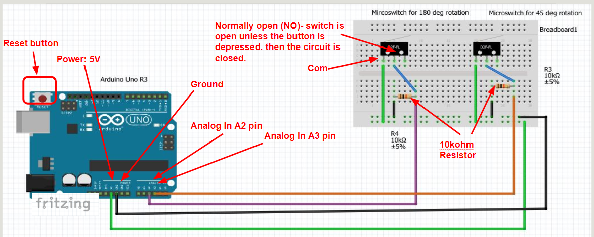
The circuit consisted of an Arduino Uno micro controller, Adafruit motor shield, two push buttons, two pull down resistors, a 12 volt/3 amp power supply, a NEMA 17 stepper motor, a NEMA 14 stepper motor and two micro switches.
Extensive testing and code debugging was the next step. Testing the adapter with the full load of the welding torch and cable allowed the device to be accurately tuned to the application. Pressing one button allowed the device to rotate on both axis until the micro switches indicated the home positions. The second button started the sequence. The total sequence time during testing was an average of 5.1 seconds.
Test day was at the end of the semester in UNCC machine shop. Seven teams competed against each other. The designs were judged by average sequence time, cost, and weight.
Team 2 finished second in the competition. Our design was the fastest to control the welding torch and cable assembly but finished second in the cost and weight categories. Team 2 was very pleased by the success of our design. We worked very well together as a team to produce a quality robot that completed the task that was assigned.


Comments