

I often use shift registers to drive 7-segment LEDs. Because it is the simplest and easiest way to do that.
When you search for 7-segment LEDs I recommend using common cathode ones. That means the GND pin is common and every LED have a different positive (V+) pin.
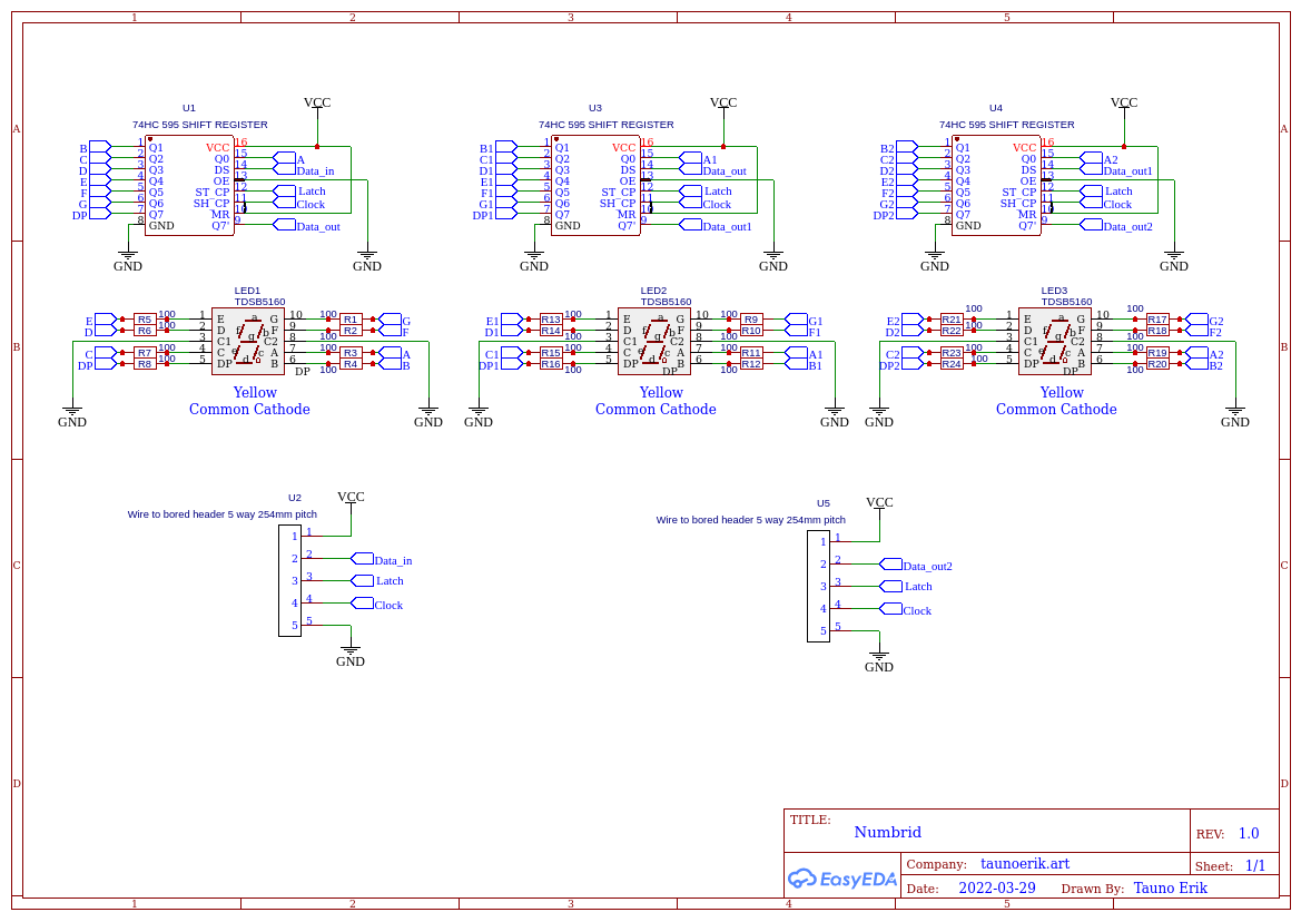
The circuit will look like this. LED pins are A, B, C, D, E, F, G and DP is a dot.
Shift register 74HC595 pins 8 and 13 are connected to GND. Pins to 16 and 10 to +5V (or to 3.3V if your board uses it ).
This is a good introduction to how to use shift registers: https://docs.arduino.cc/tutorials/communication/guide-to-shift-out
My code looks something like this:
I define Arduino pins
const uint8_t LATCH_PIN = 11;
const uint8_t CLOCK_PIN = 12;
const uint8_t DATA_PIN = 8;
define numbers in binary. 1 = LED ON and 0=LED off.
The order in 8-bit binary is dp-g-f-e-d-c-b-a
const uint8_t NUMBERS[NUM_OF_NUMS] = {
0b00111111,  // 0
0b00000110,  // 1
0b01011011,  // 2
0b01001111,  // 3
0b01100110,  // 4
0b01101101,  // 5
0b01111101,  // 6
0b00000111,  // 7
0b01111111,  // 8
0b01101111,  // 9
0b01110111,  // A
0b01111100,  // b
0b01111001,  // E
0b01110001,  // F
0b01110110,  // H
};
Set pins as output:
void setup() {
pinMode(LATCH_PIN, OUTPUT);
pinMode(CLOCK_PIN, OUTPUT);
pinMode(DATA_PIN, OUTPUT);
}
Display the numbers:
digitalWrite(LATCH_PIN, LOW);

// Number 1
shiftOut(DATA_PIN, CLOCK_PIN, MSBFIRST, NUMBERS[1]);
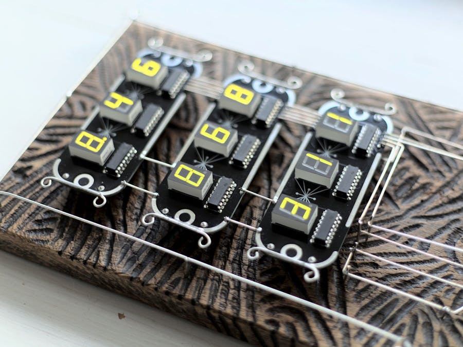
digitalWrite(LATCH_PIN, HIGH);I used these 7-segment LEDs to make my "Coat Of Arms Of The Accountant".
In this case, I made a PCB and ordered it from PCBWay. I made it that way that I can connect them together and can make a long display. If I want.


Comments