

Hardware components | ||||||
 |
| × | 1 | |||
| × | 1 | ||||
| × | 1 | ||||
| × | 1 | ||||
| × | 1 | ||||
| × | 1 | ||||
| × | 1 | ||||
| × | 1 | ||||
| × | 1 | ||||
 |
| × | 1 | |||
Software apps and online services | ||||||
| ||||||
| ||||||
| ||||||
 |
| |||||
After two months experimenting I successfully made my Smart Helmet which has some smart features such as fall & accident detection, air quality, temperature & humidity monitoring, emergency notification and obstacle detection. Definitely the hart of the system is FRDM-K82F development board along with FlexIO module. Kinetis SDK was used to develop the complete program for the system. For fall & accident detection it's built-in accelerometer FXOS8700CQ was used. Grove air quality, temperature & humidity sensor was used for monitoring air quality, temperature and humidity. I used Grove i2c RGB LCD for displaying necessary information. Grove buzzer & vibration motor was used for generating emergency alert such as when highly polluted air is detected Grove vibration motor gently vibrate to inform the user that he/she is in a highly polluted region. When user fall down accidentally buzzer generate an alert and wait for any response from the user for a specific time. If he press a button system assumes the user is OK and stop the alert otherwise it send an emergency notification to a concern person to take necessary action. I also used a RGB LED controlled by FlexIO generated PWM to show air quality information such as when air is normal or very less polluted it shows green color and for highly polluted air it shows red color.
Before going to the details of my project I like to thank NXP and Hackster for arranging such a nice competition. I again thank NXP for sending such a cool FRDM-K82F development board and without this it was not possible for me to make such thing. I also thank Adam Benzion and Donnie Garcia whose Webinar was really helpful for me.
I will explain my project in step by step with helping image & code. Let's start...
Reading on-board accelerometer data using FlexIO I2CThe FlexIO module was first introduced in the Freescale Kinetis KL43 family. It is capable of emulating various serial communication protocols including: UART, SPI and I2C. The FlexIO module is very flexible and you can configure it according to your communication needs. (NXP)
FRDM-k82F has an on board accelerometer connected to Kinetis MCU using i2c bus. SDA pin of accelerometer FXOS8700CQ is connected to PTA1 and SCL pin is connected to PTA2. This two pins are flexio enable and PTA1 is FLEXIO_D11, PTA2 is FlEXIO_D12.
Kinetis SDK folder contains an excellent example program to read the accelerometer data using FlexIO i2c. You need to slightly modify the pin definition as shown in the image below. You also need to modify the pin_mux.c as shown in the screen shot. For details follow the Webinar 2.
I used Grove I2C RGB LCD module with FRDM-K82F board to display necessary information and FlexIO I2C module was used to interfacing the display with FRDM board.
FRDM-K82F board is fully compatible to Arduino Uno pin header. So, I used Seeed Studio Base shield to connect Grove modules. As I used Grove I2C LCD display so I used I2C header of the Base shield to connect the display. I used this header because it is actually PTA1 (SDA) & PTA2 (SCL) pin of the board to which accelerometer is connected. As you know, using same i2c bus we can communicate with several i2c devices as every device type has unique I2C address. For taking the advantage I selected same i2c bus for accelerometer and LCD display.
For interfacing the display I hacked Grove Arduino library for Grove RGB LCD. I converted the corresponding Arduino statements for the FlexIO i2c. Here is the complete program for the LCD. You also find it to my Github.
#include <stdio.h>
#include <string.h>
/*  SDK Included Files */
#include "main.h"
#include "rgb_lcd.h"
/*******************************************************************************
* Definitions
******************************************************************************/
// FlexIO for LCD
#define BOARD_FLEXIO_BASE FLEXIO0          // Defines the FlexIO instance to be used
#define FLEXIO_I2C_SDA_PIN (11U)           // Defines the FlexIO pin to be used for the SDA pin
#define FLEXIO_I2C_SCL_PIN (12U)           // Defines the FlexIO pin to be used for the SCL pin
#define FLEXIO_CLOCK_FREQUENCY (12000000U) // Defines the clock frequency used in the application
#define I2C_BAUDRATE (100000) /* 100K */   // Defines the I2C baud rate
#define LCD_ADDRESS     (0x7c>>1)
#define RGB_ADDRESS     (0xc4>>1)
#define CLK_SPEED 150U //Put your board's clock speed here in MHz, FRDM-K82f = 150
/*******************************************************************************
* Prototypes
******************************************************************************/
static bool I2C_write_lcd(FLEXIO_I2C_Type *base, uint8_t device_addr, uint8_t reg_addr, uint8_t value);
void delay(int time);
void rgb_lcd_init();
void rgb_lcd_write(char *data);
void rgb_led_init();
void rgb_lcd_clear();
void rgb_lcd_set_cursor(uint8_t col, uint8_t row);
/*******************************************************************************
* Variables
******************************************************************************/
uint8_t readBuff[2];
uint8_t g_master_buff[3];
flexio_i2c_master_handle_t g_m_handle;
FLEXIO_I2C_Type i2cDev;
uint32_t gStateBufferPos[8] = {0};
uint8_t status0_value = 0;
volatile bool completionFlag = false;
volatile bool nakFlag = false;
extern volatile uint8_t fxioState;
uint8_t command_reg = 0;
uint8_t data_reg = 0;
uint8_t command = 0;
/*******************************************************************************
* Code
******************************************************************************/
static void flexio_i2c_master_callback(FLEXIO_I2C_Type *base,
                            flexio_i2c_master_handle_t *handle,
                            status_t status,
                            void *userData)
{
/* Signal transfer success when received success status. */
if (status == kStatus_Success)
{
completionFlag = true;
}
/* Signal transfer success when received success status. */
if (status == kStatus_FLEXIO_I2C_Nak)
{
nakFlag = true;
}
}
static bool I2C_write_lcd(FLEXIO_I2C_Type *base, uint8_t device_addr, uint8_t reg_addr, uint8_t value)
{
flexio_i2c_master_transfer_t masterXfer;
memset(&masterXfer, 0, sizeof(masterXfer));
masterXfer.slaveAddress = device_addr;
masterXfer.direction = kFLEXIO_I2C_Write;
masterXfer.subaddress = reg_addr;
masterXfer.subaddressSize = 1;
masterXfer.data = &value;
masterXfer.dataSize = 1;
/*  direction=write : start+device_write;cmdbuff;xBuff; */
/*  direction=recive : start+device_write;cmdbuff;repeatStart+device_read;xBuff; */
FLEXIO_I2C_MasterTransferNonBlocking(&i2cDev, &g_m_handle, &masterXfer);
/*  Wait for transfer completed. */
while ((!nakFlag) && (!completionFlag))
{
}
nakFlag = false;
if (completionFlag == true)
{
completionFlag = false;
return true;
}
else
{
return false;
}
}
void delay(int time)
{
uint32_t delayNum = (CLK_SPEED / 15) * time; //as clock speed in MHz, delay is in us
volatile uint32_t cnt = 0U;
for(cnt = 0U; cnt < delayNum; ++cnt){
	  __asm("NOP");
}
}
void rgb_lcd_init()
{
	// SEE PAGE 45/46 of LCD Datasheet FOR INITIALIZATION SPECIFICATION!
	// according to datasheet, we need at least 40ms after power rises above 2.7V
	// before sending commands. Freedom board can turn on way befer 4.5V so we'll wait 50
	delay(50000);  //50ms
	// this is according to the hitachi HD44780 datasheet
	// page 45 figure 23
	// Send function set command sequence
	command_reg =0x80;
	command = 0x28;
	I2C_write_lcd(&i2cDev, LCD_ADDRESS, command_reg, command);
	delay(4500);  //4.5 ms
	// second try
	I2C_write_lcd(&i2cDev, LCD_ADDRESS, command_reg, command);
	delay(150);
	// third go
	I2C_write_lcd(&i2cDev, LCD_ADDRESS, command_reg, command);
	command = 0x0C;  //LCD_DISPLAYON , LCD_CURSOROFF , LCD_BLINKOFF;
	I2C_write_lcd(&i2cDev, LCD_ADDRESS, command_reg, command);
	command = 0x01;  // clear it off
	I2C_write_lcd(&i2cDev, LCD_ADDRESS, command_reg, command);
	delay(2000);    // this command takes long time
	command = 0x0C;  // Initialize to default text direction
	I2C_write_lcd(&i2cDev, LCD_ADDRESS, command_reg, command);
}
void rgb_lcd_clear()
{
	command_reg =0x80;
	command = 0x01;  // clear it off
	I2C_write_lcd(&i2cDev, LCD_ADDRESS, command_reg, command);
	delay(2000);    // this command takes long time
}
void rgb_lcd_set_cursor(uint8_t col, uint8_t row)
{
command = (row == 0 ? col|0x80 : col|0xc0);
command_reg =0x80;
I2C_write_lcd(&i2cDev, LCD_ADDRESS, command_reg, command);
}
void rgb_lcd_write(char *data)
{
	 uint32_t i = 0;
	 data_reg = 0x40;
	 for(i=0;i<strlen(data);i++)
	 {
	 	I2C_write_lcd(&i2cDev, LCD_ADDRESS, data_reg, data[i]);
	 }
}
void rgb_led_init()
{
	//Reset
	 command_reg = REG_MODE1;
	 command = 0x00;
	 I2C_write_lcd(&i2cDev, RGB_ADDRESS, command_reg, command);
	 /*  Function set */
	 command_reg = REG_OUTPUT;
	 command = 0xFF;
	 I2C_write_lcd(&i2cDev, RGB_ADDRESS, command_reg, command);
	 command_reg = REG_MODE2;
	 command = 0x20;
	 I2C_write_lcd(&i2cDev, RGB_ADDRESS, command_reg, command);
	 /* Color Set */
	 command_reg = REG_GREEN;
	 command = 0xFF;          //amount of green 0 - 255
	 I2C_write_lcd(&i2cDev, RGB_ADDRESS, command_reg, command);
	 command_reg = REG_RED;
	 command = 0xFF;          //amount of red 0 - 255
	 I2C_write_lcd(&i2cDev, RGB_ADDRESS, command_reg, command);
	 command_reg = REG_BLUE;
	 command = 0xFF;          //amount of blue 0 - 255
	 I2C_write_lcd(&i2cDev, RGB_ADDRESS, command_reg, command);
}
/*!
* @brief Main function
*/
int main(void)
{
BOARD_InitPins();
BOARD_BootClockRUN();
BOARD_InitDebugConsole();
flexio_i2c_master_config_t masterConfig;
CLOCK_SetFlexio0Clock(2U);
/*do hardware configuration*/
i2cDev.flexioBase = BOARD_FLEXIO_BASE;
i2cDev.SDAPinIndex = FLEXIO_I2C_SDA_PIN;
i2cDev.SCLPinIndex = FLEXIO_I2C_SCL_PIN;
i2cDev.shifterIndex[0] = 0U;
i2cDev.shifterIndex[1] = 1U;
i2cDev.timerIndex[0] = 0U;
i2cDev.timerIndex[1] = 1U;
/*
* masterConfig.enableMaster = true;
* masterConfig.enableInDoze = false;
* masterConfig.enableInDebug = true;
* masterConfig.enableFastAccess = false;
* masterConfig.baudRate_Bps = 100000U;
*/
FLEXIO_I2C_MasterGetDefaultConfig(&masterConfig);
masterConfig.baudRate_Bps = I2C_BAUDRATE;
/* Initialize FlexIO I2C master and handle for interrupt */
FLEXIO_I2C_MasterInit(&i2cDev, &masterConfig, FLEXIO_CLOCK_FREQUENCY);
FLEXIO_I2C_MasterTransferCreateHandle(&i2cDev, &g_m_handle, flexio_i2c_master_callback, NULL);
// lcd initialization
rgb_lcd_init();
rgb_led_init();
	rgb_lcd_write("Hello World!");
	delay(10000000);
	rgb_lcd_set_cursor(5,1);
	rgb_lcd_write("Allahu");
	delay(1000);
rgb_lcd_clear();
for(;;) { /* Infinite loop to avoid leaving the main function */
__asm("NOP"); /* something to use as a breakpoint stop while looping */
}
}
Grove air quality sensor provides analog data. So, you need analog conversion to get the air quality data. I connected Air quality sensor to the A1 header of the base shield. A1 header is PTC1 pin of the FRDM board which is SE15. If you want to test connect Air Quality sensor to A1 header, upload the following program and enjoy. Of course you can use different analog header with proper modification into the program. You can download the complete program from my Github repository.
Example program using Kinetis SDK
#include "board.h"
#include "fsl_adc16.h"
#include "pin_mux.h"
#include "clock_config.h"
/*******************************************************************************
* Definitions
******************************************************************************/
#define DEMO_ADC16_BASE ADC0
#define DEMO_ADC16_CHANNEL_GROUP 0U
#define DEMO_ADC16_USER_CHANNEL 15U //se15  | 23 PTC1 | Arduino ADC pin 2
/*******************************************************************************
* Prototypes
******************************************************************************/
/*******************************************************************************
* Variables
******************************************************************************/
volatile uint32_t g_Adc16ConversionValue;
/*******************************************************************************
* Code
******************************************************************************/
/*!
* @brief Main function
*/
int main(void)
{
adc16_config_t adc16ConfigStruct;
adc16_channel_config_t adc16ChannelConfigStruct;
BOARD_InitPins();
BOARD_BootClockRUN();
BOARD_InitDebugConsole();
/*
* adc16ConfigStruct.referenceVoltageSource = kADC16_ReferenceVoltageSourceVref;
* adc16ConfigStruct.clockSource = kADC16_ClockSourceAsynchronousClock;
* adc16ConfigStruct.enableAsynchronousClock = true;
* adc16ConfigStruct.clockDivider = kADC16_ClockDivider8;
* adc16ConfigStruct.resolution = kADC16_ResolutionSE12Bit;
* adc16ConfigStruct.longSampleMode = kADC16_LongSampleDisabled;
* adc16ConfigStruct.enableHighSpeed = false;
* adc16ConfigStruct.enableLowPower = false;
* adc16ConfigStruct.enableContinuousConversion = false;
*/
ADC16_GetDefaultConfig(&adc16ConfigStruct);
ADC16_Init(DEMO_ADC16_BASE, &adc16ConfigStruct);
ADC16_EnableHardwareTrigger(DEMO_ADC16_BASE, false); /* Make sure the software trigger is used. */
#if defined(FSL_FEATURE_ADC16_HAS_CALIBRATION) && FSL_FEATURE_ADC16_HAS_CALIBRATION
if (kStatus_Success == ADC16_DoAutoCalibration(DEMO_ADC16_BASE))
{
PRINTF("ADC16_DoAutoCalibration() Done.\r\n");
}
else
{
PRINTF("ADC16_DoAutoCalibration() Failed.\r\n");
}
#endif /* FSL_FEATURE_ADC16_HAS_CALIBRATION */
adc16ChannelConfigStruct.channelNumber = DEMO_ADC16_USER_CHANNEL;
adc16ChannelConfigStruct.enableInterruptOnConversionCompleted = false; /* Enable the interrupt. */
#if defined(FSL_FEATURE_ADC16_HAS_DIFF_MODE) && FSL_FEATURE_ADC16_HAS_DIFF_MODE
adc16ChannelConfigStruct.enableDifferentialConversion = false;
#endif /* FSL_FEATURE_ADC16_HAS_DIFF_MODE */
while (1)
{
	for(int i =0; i<1000000; i++)
	{
		__asm("NOP");
	}
/*
When in software trigger mode, each conversion would be launched once calling the "ADC16_ChannelConfigure()"
function, which works like writing a conversion command and executing it. For another channel's conversion,
just to change the "channelNumber" field in channel configuration structure, and call the function
"ADC16_ChannelConfigure()"" again.
Also, the "enableInterruptOnConversionCompleted" inside the channel configuration structure is a parameter for
the conversion command. It takes affect just for the current conversion. If the interrupt is still required
for the following conversion, it is necessary to assert the "enableInterruptOnConversionCompleted" every time
for each command.
*/
ADC16_SetChannelConfig(DEMO_ADC16_BASE, DEMO_ADC16_CHANNEL_GROUP, &adc16ChannelConfigStruct);
while (kADC16_ChannelConversionDoneFlag != ADC16_GetChannelStatusFlags(DEMO_ADC16_BASE, DEMO_ADC16_CHANNEL_GROUP))
{
}
g_Adc16ConversionValue = ADC16_GetChannelConversionValue(DEMO_ADC16_BASE, DEMO_ADC16_CHANNEL_GROUP);
PRINTF("ADC Value: %d\r\n", g_Adc16ConversionValue);
if(g_Adc16ConversionValue < 100){
	PRINTF("Low Pollution");
}
else if(g_Adc16ConversionValue > 100 && g_Adc16ConversionValue < 400){
  PRINTF("High Pollution");
}
else if(g_Adc16ConversionValue > 400){
  PRINTF("Very High Pollution");
              }
}
}
Grove Temperature & Humidity sensor (DHT11) provides 40 bits temperature and humidity data when host (MCU) sends a start signal. It is one wire data transmission. Host should send a low signal for at least 18ms. When dht11 sensor detects an external low signal then it sends an 80us response signal followed by a 80us ready signal to the microcontroller. Then sends 40 bits data (8 bit humidity integer data + 8 bit decimal data + 8 bit temperature integer data + 8 bit decimal data + 8 bit parity). Microprocessor should receive this 40 bit serial data. So, thing you already understand that microcontroller pin first act as output pin and then receive data as input pin. For details about the data transmission check DHT11 datasheet.
Example program
Connect Grove temperature and humidity sensor to D5 header which is PTC10 of the FRDM-K82F board. After connecting you may upload the following program to read temperature & humidity from the sensor. You can download the complete program from my Github.
#include "main.h"
#define CLK_SPEED 150U
// how many timing transitions we need to keep track of. 2 * number bits + extra
#define MAXTIMINGS 85
#define SENSOR GPIOC
#define TEMP_HUMID_PIN 10U  // D5 in base shild
uint8_t data[6];
int i, j = 0;
int counter = 0, count = 6;
bool laststate = 1;
float f;
bool read_temp_humidity();
void delay(int time)
{
uint32_t delayNum = (CLK_SPEED / 15) * time; //as clock speed in MHz, delay is in us
volatile uint32_t cnt = 0U;
for(cnt = 0U; cnt < delayNum; ++cnt){
	  __asm("NOP");
}
}
bool read_temp_humidity(){
	gpio_pin_config_t pin_config_output =
		 {
				 kGPIO_DigitalOutput,1, // pin as output
		 };
	gpio_pin_config_t pin_config_input =
	 	 {
	 			 kGPIO_DigitalInput,0,  // pin as input
	 	 };
	GPIO_PinInit(SENSOR, TEMP_HUMID_PIN, &pin_config_output);
	GPIO_WritePinOutput(SENSOR, TEMP_HUMID_PIN, 1);  // output high
	delay(250000);                       // wait for 250ms
// 20ms low pulse from the master to initiate communication
	// check DHT11 datasheet for details information
	GPIO_WritePinOutput(SENSOR, TEMP_HUMID_PIN, 0);  // output low
	delay(20000);                        // wait for 20ms
	GPIO_WritePinOutput(SENSOR, TEMP_HUMID_PIN, 1);  // output high
	delay(40);                           // wait 40us
// configure the pin as input to receive data from dht sensor
	GPIO_PinInit(SENSOR, TEMP_HUMID_PIN, &pin_config_input);
	// dht sensor transmit 40 bits data
	data[0] = data[1] = data[2] = data[3] = data[4] = 0;
	counter = 0; j = 0; laststate = 1;
	  //
	for ( i=0; i< MAXTIMINGS; i++) {
	    counter = 0;
	    while (GPIO_ReadPinInput(SENSOR, TEMP_HUMID_PIN) == laststate) {
	        counter++;
	        delay(10);
	        if (counter == 255) {
	          break;
	        }
	      }
	    laststate = GPIO_ReadPinInput(SENSOR, TEMP_HUMID_PIN);
	    if (counter == 255) break;
	    // ignore first 3 transitions
	    if ((i >= 4) && (i%2 == 0)) {
	        // save each bit into the storage bytes
	       data[j/8] <<= 1;
	       if (counter > count)
	          data[j/8] |= 1;
	       j++;
	      }
}
// check 8bit parity to confirm the receive data is correct
	if ((j >= 40) &&
	      (data[4] == ((data[0] + data[1] + data[2] + data[3]) & 0xFF)) ) {
	    return true;
	  }
	return false;
}
int main(void) {
BOARD_InitPins();
BOARD_BootClockRUN();
BOARD_InitDebugConsole();
for(;;) { /* Infinite loop to avoid leaving the main function */
	 		read_temp_humidity();
	 		//if(read_temp_humidity())
	 		  PRINTF("%d%%RH\t%d C\r\n",data[0],data[2]);
	 		delay(1000000);
/* something to use as a breakpoint stop while looping */
}
}
I want to display air quality information using RGB LED. Brightness and color of RGB LED can be control easily using PWM output. I want to show green color for low pollution, low intensity red for high polution and high intensity red for very high pollution. FlexIO module was used to generate PWM output.
The FlexIO module is capable of generating a PWM signal by configuring one of its timers to the Dual 8-bit counters PWM mode. This mode is configured by writing 01 to TIMOD in the TIMCTL register. In this mode, the lower 8-bits of the counter and compare register are used to configure the high period of the timer output and the upper 8-bits are used to configure the low period of the timer output.
To calculate the frequency of the PWM signal we have to add the lower 8-bits of the counter and the upper 8-bits and divide it by the FlexIO clock*2 (Only if the timer is configured to decrement on the FlexIO clock.)
The frequency of the PWM signal is given by:
f = (FlexIO clock)/(TIMCMP[15:8]+TIMCPM[7:0]+2)
Generating PWM requires the following resources:
i. One FlexIO pin
ii. One FlexIO timer
FlexIO pin is configured as output and timer is configured as Dual 8-bit PWM mode. Timer compare value can be calculated by following formula.
Timer compare value = (((FLEXIO_CLK / freq) * (100 - duty) / 100 - 1) << 8) | ((FLEXIO_CLK / freq) * duty / 100 - 1)
The timer compare value is loaded into the timer counter when the timer is first enabled, when the timer is reset or decreased to 0. Enter the dual 8-bits value into this compare register to load the value to ensure every cycle of the PWM has the timer counter reloaded from CMP. This compare value controls the PWM frequency and duty.
For controlling brightness frequency is not so important, the important factor is the duty cycle. For example we will get maximum brightness for 100% duty and minimum for 0% duty.
Example code for FlexIO PWM in the PTC8 pin which is FLEXIO_D16 and compatible to Arduino D6 pin.
/*defining the pin for pwm, PTC8 is FlexIO 16 as shown previous figure */
#define FLEXIO_PWM_PIN 16U   //Arduino D6
/////////////////////////////////////////////////////////////////////////
flexio_timer_config_t timerConfig;
CLOCK_EnableClock(kCLOCK_Flexio0);  //enabling flexio clock
FLEXIO_Enable(FLEXIO0, true);  //enableing flexio module
/////////////////////////////////////////////////////////////////////////
/* flexio timmer configuretion, timer 5 was used */
timerConfig.triggerSelect = FLEXIO_TIMER_TRIGGER_SEL_SHIFTnSTAT(0);
o effect in pwm
timerConfig.triggerPolarity = kFLEXIO_TimerTriggerPolarityActiveLow;/
o effect in pwm
timerConfig.triggerSource = kFLEXIO_TimerTriggerSourceInternal; //internal
timerConfig.pinConfig = kFLEXIO_PinConfigOutput;  //as output for pwm
timerConfig.pinSelect = FLEXIO_PWM_PIN;   //pin for pwm output
timerConfig.pinPolarity = kFLEXIO_PinActiveHigh;  //active high
timerConfig.timerMode = kFLEXIO_TimerModeDual8BitPWM; //pwm mode
timerConfig.timerOutput = kFLEXIO_TimerOutputOneNotAffectedByReset;
//initial output high
timerConfig.timerDecrement = kFLEXIO_TimerDecSrcOnFlexIOClockShiftTimerOutput;
//decrement for flexio clock
timerConfig.timerReset = kFLEXIO_TimerResetNever; /
ever reset for pwm
timerConfig.timerDisable = kFLEXIO_TimerDisableNever;/
ever disable
timerConfig.timerEnable = kFLEXIO_TimerEnabledAlways;//always enable for pwm
timerConfig.timerStop = kFLEXIO_TimerStopBitDisabled;    //stop bit disable
timerConfig.timerStart = kFLEXIO_TimerStartBitDisabled;  //start bit disable
////////////////////////////////////////////////////////////////////////////
/* Set TIMCMP[15:8] = Low pulse width, TIMCMP[7:0] = high pulse width */
timerConfig.timerCompare = 0x0FFF; //value for duty cycle
FLEXIO_SetTimerConfig(FLEXIO0, 6, &timerConfig); //starting timer
///////////////////////////////////////////////////////////////////////////
I used FlexIO module to interface Grove Ultrasonic ranger to FRMD-K82F board. PTC1 pin is acting as trigger and echo pin. This pin act as general output pin and generate a 5 microsecond pulse to impose trigger to the sonar. Then this pin act as a FlexIO pin using pin muxing. This pin is FelxIO 13 (Alt7). To calculate the distance of obstacle two FlexIO timer & 5 FlexIO shifter was used. As timer 0,1 and shifter 0, 1 was used in i2c driver and for that I used timer 2, 3 and shifter 2-6 for the purpose. The concept behind the interfacing is that, when sonar is triggered then it generate a high pulse to its echo pin and the duration of the pulse is proportional to the distance of obstacle from the ranger. Timer 2 is enable at the starting of echo pulse and start to decremented. A value is set to compare register which reduced to zero within a specific time which is nothing but the duration for the distance of 1 cm. The value depends on FlexIO clock and the resolution. After reducing the value of the compare register to zero timer 2 trigger the timer 3 and timer 3 trigger shifter to shift 1 bit to buffer register. When echo pulse become low timers become disabled. Total shifted bits from the buffers are read which is equal to the distance in centimeter.
(Idea for the source code of distance measurement was taken from the project Kinetis FlexIO Ultrasonic Radar developed by Mirko Denecke. So, special thanks to Mirko Denecke for nice Idea).
Algorithm is based on the concept that, during a fall, a person experiences a momentary freefall or reduction in acceleration, followed by a large spike in acceleration, then a change in orientation. The flowchart for Algorithm is given below. We see the algorithm checks to see if the acceleration magnitude (AM) breaks a set lower threshold. If this lower threshold is broken, the algorithm then checks to see if AM breaks a set upper threshold within 0.5s. If this upper threshold is broken, the algorithm then checks to see if the person’s orientation has changed in a set range within 0.5s, which would indicate a person has fallen or toppled over. If the person’s orientation has changed, the algorithm then examines to see if that orientation remains after 10s, which would indicate the person is immobilized in their fallen position on the ground. If this holds true, the algorithm recognizes this as a fall. A failure of any of the intermediate decision conditions would reset the triggers and send you back to the start. The strength of this algorithm is that it requires an activity to break two AM thresholds and have an orientation change. Ideally this additional lower threshold would reduce the number of false positives. The weakness of this algorithm is that it requires the fall to involve an orientation change.
For adding emergency notification feature follow my tutorial Emergency Fall Notifier with Panic Button where all necessary steps are explained in details.
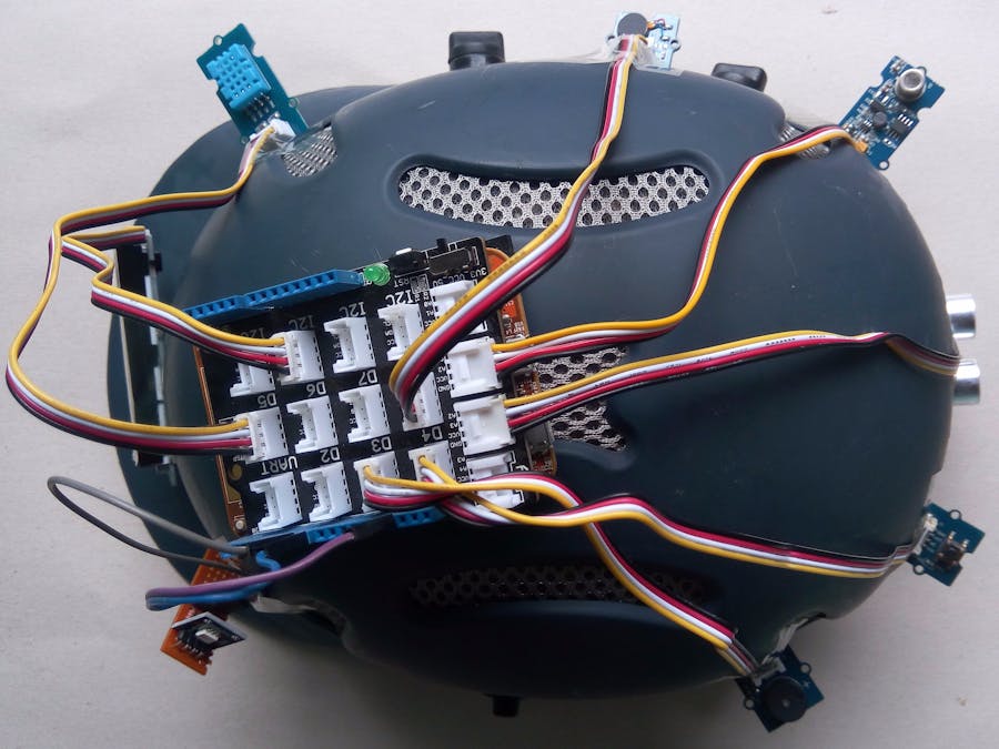
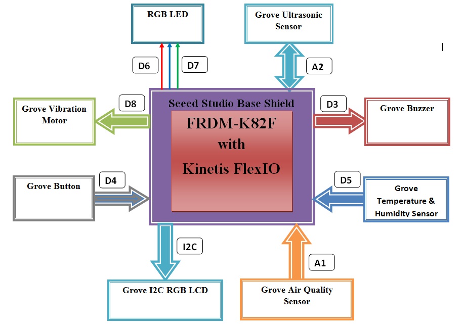
Complete SetupConnect all the sensors and modules with base shield and FRDM board as shown in the image below. You can take help of the block diagram attached in the schematic section where header number for each sensors and modules are clearly mentioned.
Setup the connected system to the helmet to make it smart. Keep the Ultrasonic Ranger to the back side & LCD display in the front side. Other sensors may be placed in any convenient location. Try to keep the button in an easy accessible location as you will press it frequently for several purpose. Li-ion rechargeable battery may be a good option as power source but for demo purpose I used a power bank. I set all sensors temporarily using scotch tape. Hot glue may be another good option to fixed all tightly to the helmet.
- FRDM-K82F User’s Guidehttp://cache.nxp.com/files/32bit/doc/user_guide/FRDMK82FUG.pdf
- FRDM-K82F Schematics - http://cache.nxp.com/files/32bit/hardware_tools/schematics/FRDM-K82F-SCH.pdf
- MK82 Datasheet - http://cache.nxp.com/files/32bit/doc/data_sheet/K82P121M150SF5.pdf
- MK82 Reference Manual - http://cache.nxp.com/files/32bit/doc/ref_manual/K82P121M150SF5RM.pdf
- Kinetis SDK 2 API Reference Manual-http://cache.nxp.com/files/soft_dev_tools/doc/support_info/KSDK20APIRM.pdf
- Generating PWM by Using FlexIO - NXP - http://www.nxp.com/files/32bit/doc/app_note/AN5209.pdf?fasp=1&WT_TYPE=Application%20Notes&WT_VENDOR=FREESCALE&WT_FILE_FORMAT=pdf&WT_ASSET=Documentation&fileExt=.pdf
- Grove LCD RGB Backlight - www.mouser.com/catalog/specsheets/Seeed_104030001.pdf
- DHT11 - Temperature & Humidity Sensor Datasheet - www.micropik.com/PDF/dht11.pdf
- Grove - Air Quality Sensor - http://www.seeedstudio.com/wiki/Grove_-_Air_Quality_Sensor
- Grove - Ultrasonic Ranger - http://www.seeedstudio.com/wiki/Grove_-_Ultrasonic_Ranger


Comments