

Hardware components | ||||||
| × | 1 | ||||
| × | 1 | ||||
| × | 1 | ||||
| × | 1 | ||||
 |
| × | 2 | |||
| × | 1 | ||||
 |
| × | 2 | |||
 |
| × | 2 | |||
 |
| × | 1 | |||
| × | 1 | ||||
 |
| × | 1 | |||
| × | 2 | ||||
| × | 1 | ||||
| × | 1 | ||||
| × | 1 | ||||
 |
| × | 1 | |||
| × | 2 | ||||
Hand tools and fabrication machines | ||||||
 |
| |||||
 |
| |||||
 |
| |||||
| ||||||
 |
| |||||
| ||||||
 |
| |||||
 |
| |||||
| ||||||
| ||||||
In my home, the main hallway from the living room to the bedrooms has always been dark. The existing light in the hall is controlled by a switch halfway between the living room and the bedrooms, with the light being directly above the intersection of the rooms. This does almost nothing to illuminate the hall, and any family photos on the walls are difficult to see. Add to the mix an 8-year-old that is afraid of the dark, I wanted to solve a small problem with overkill!
Insert this project! I knew from the start that I wanted a way to have lights come on without needing to flip a switch. I was aware of Passive Infrared Sensors (PIR), and other ways to trigger lights, but had little experience with Arduino projects. I looked into LED strips with motion sensors, but everything I saw was either the wrong fit for my hall, or relied on an outlet I didn't have nearby.
I had tinkered with the Raspberry Pi 3 before, and have taken a few coding classes, so when I heard of Arduino, I was intrigued. I saw tons of projects online, and the tutorial videos I watched made Arduino seem like the right way to go. It wasn't long before I picked up the 101 Sensor Basics kit from OSEPP. After doing a few of the projects to get a feel for how to upload a sketch to my Arduino R4, I started gathering materials!
The Basic SetupOnce I felt comfortable using the breadboard and uploading sketched to the Arduino, I started looking for how I could combine what I knew to get what I want. The PIR sensor that comes with the 101 Sensor Basics kit from OSEPP gave me the code and practice to incorporate a couple into my project.
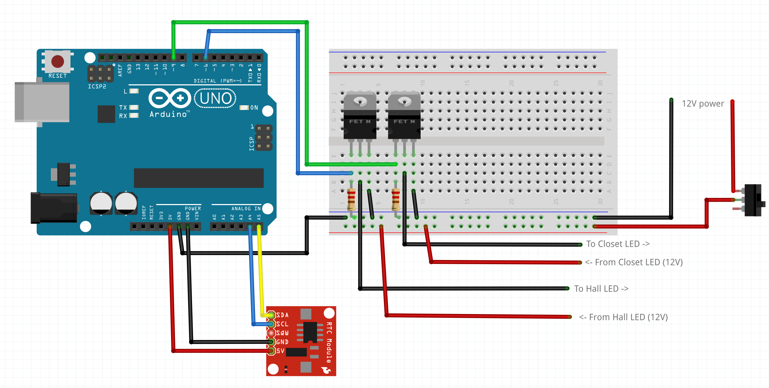
After getting the components together, I began by looking at The Ultimate Guide To Connecting LED Strips to Arduino. This article was exactly what I needed to get the lights connected using my n-channel MOSFETs. Until this site came along, I didn't really know how to connect all the pieces. My biggest take away from that site was the diagram below:
After connecting the setup as indicated (for testing), I went to my computer and fired up the Arduino software to write the program. My finished code is in the "Code" section.
I used Ian's code to get everything working, then used the code from the OSEPP Starter kit to incorporate the PIR sensors. Once I got the sensors to work, I messed around with the dimmer settings.
It was about this time that my wife started pointing out all the ways she hated my project, and gave me valuable input! Because of her constructive criticism, I looked at adding a switch that turns off the LED strip power and using a Real-Time Clock to keep track of the hours in the day.
With this guide to using RTC with Arduino, I was able to figure out which libraries to import. In the Arduino software, you will need to import the RTClib library by Adafruit, the Time library, and the DS1307RTC library by Michael Margolis.
When connecting the RTC board to the Arduino, I had the following connections:
- SCL on the RTC connected to A5 (Analog pin #5) on the Arduino
- SDA on the RTC connected to A4 (Analog pin #4) on the Arduino
- VCC on the RTC connected to a 5V pin on the Arduino
- GND on the RTC connected to a GND on the Arduino
(For testing purposes, and because it was easier, I plugged the RTC board into the breadboard, then used jumpers to make the connections.)
After combining the different programs, and tweaking functions and variables here and there, I am able to have each PIR sensor trigger its individual strip, dimming it up to a certain level dependent on the current hour of the day. I have mine set to change to the "Night Mode" at 9pm, and go back to "Day mode" at 9am. Once I was happy with my code, I uploaded it one final time and connected the Arduino to a USB power supply and watched my creation work!
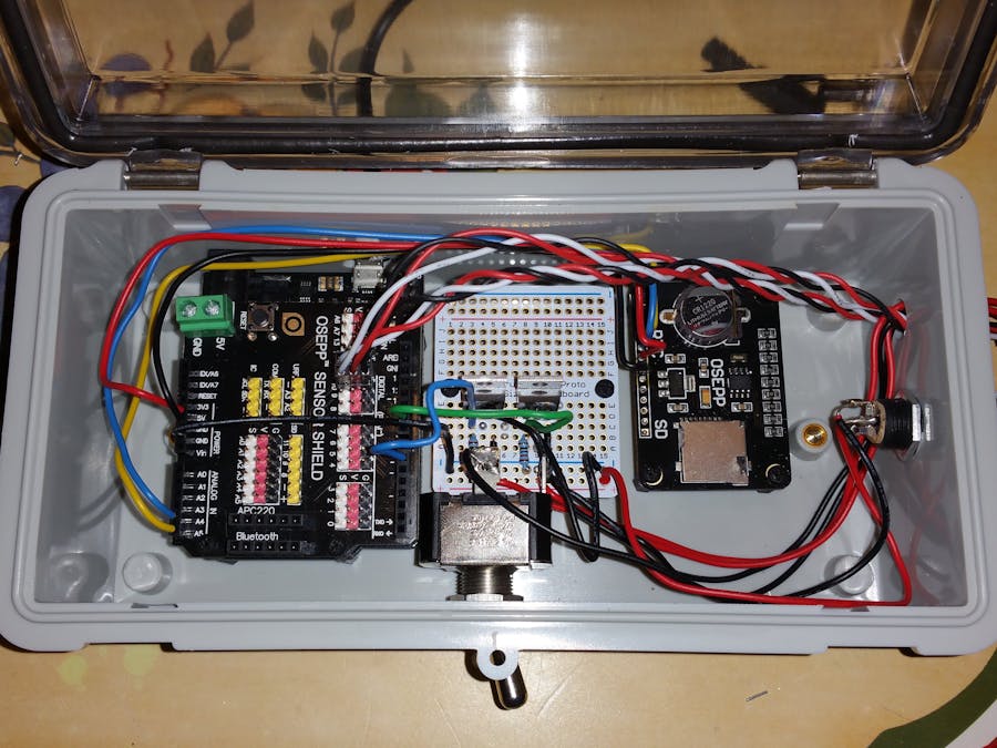
Soldering All the ThingsOnce everything was working, I wanted to work on my soldering skills and make this not look like a rat's nest of jumper cables in a breadboard. I strongly recommend using colored cable and/or labels on the wires that come out of the project box to help you keep track of which wire goes where...
First, I put the Arduino, the Perma-Proto board, and the RTC in my project box to mark where to drill the holes for the standoffs with a fine-tipped Sharpie. To get the right size hole, use one of the screws in the standoff kit as a guide and pick a drill bit that is slightly bigger than the screw threading, but not as big as the screw head. After drilling the holes and testing the fit, I marked where I wanted the switch, and where I will plug in an optional DC connector in the sides of the box. Then, I drilled the hole through which the wires for the PIR sensors and LED strip power will pass. Last, I marked and cut out the hole for the microUSB cable that will power the board.
Once the holes were drilled, I found the right sizes of standoffs and screws for the Arduino and the Sensor Shield, and mounted them. Then, using my breadboard setup as a guide, I soldered the non-RTC wires to the Perma-Proto board leaving enough extra cable to be routed and connected to the Sensor Shield pins.
Next, I used my soldering iron to remove the header pins from the RTC board and soldered lengths of wire to the pins as indicated before, but without the breadboard. After connecting them to the appropriate pins, I soldered the power switch to the "-" rail on the Perma-Proto board and to a terminal on the DC jack I used. I soldered the other DC jack terminal to the "+" rail on the Perma-Proto board, completing the main chunk of the project!
Once the solder cooled, I wanted to make sure I didn't fry anything or miss a connection, so I fired up my new contraption to see if it still worked. To my surprise, it did! I buttoned it all up and went about mounting the device in my hall closet. Drywall anchors came in handy for the project box...
After determining the location for my lights, I measured the ceiling to find the midpoint and found the length I would need for my hall. Then I made a center line to follow while screwing in the mounting clips for the rail system. I took my length measurement and cut one of the rails down to size with my hacksaw and a miter box, including the plastic diffusing shield. I used one of the connecting clips to keep the sections together while I peeled and stuck the LED strip to the inside of the rail. I cut off the excess LED strip, making sure not to leave any hanging out of the rail, and attached the diffusing plastic. I swapped the position of the plastic diffusers to give the joint more rigidity.
When the hallway LED rail was complete, I did the same steps with the closet LED rails, and intended to use the L-connectors I bought, but I started getting anxious to see the project done, and I had already cut the top rail to fit my closet door frame just a little too wide. From this point, it was time to put up the rails!
I installed the mounting clips for the rails, then clipped in the LED rail in the hallway. I drilled a hole in my ceiling big enough for my wires to fit, and left it like that while I did the same for the closet LEDs. I have a good place to mount my project box in the hall closet, so I drilled two holes in the ceiling in there for all the connecting wires to pass (one for the micro USB power and one for the 12VDC power supply). I then used a measuring tape to see how long my wires needed to be for each device and cut a few pieces to length.
For the PIR sensors, I just used the three-pin jumper cables that came with the 101 Sensor Basics kit. No solder there, just heat shrink to keep it together. I mounted one sensor each in the hallway and the closet. I ended up using anchored zip ties to keep the wires somewhat neat.
Finally! The time has come! Plug in the Arduino! Plug in the DC power supply for the LEDs! In my case, the lights didn't come on. (I forgot to flip the switch for the LED strips...) After some troubleshooting, and a few more tweaks to the code, my project is finally finished! Check out the before/after...
After messing with this project for a few days/weeks, there are a few things I might do differently.
First, I might reconsider using the Passive Infrared sensors. I originally wanted to use a light beam (like on garage door openers) for the hallway, and a magnetic switch on the closet door. These make more sense for the application, but I didn't have those things to tinker with, and I liked the idea of PIR sensors.
Next, I would find a way to hook up a dimmer knob somewhere easily accessible that would bypass the Arduino controller when turned on. This way, if we want more light on demand, it's there.
Also, the lowest brightness setting that the LED strips can manage may still be a little too bright for those late-night trips to the kitchen. I will probably get addressable LED strips in the future. Configuring and controlling different zones would be nice!
Finally, I would look into different types of wire connectors. I wanted to get Molex connectors, but I also wanted to practice my soldering skills. (If you look closely at the Perma-Proto board, and the RTC, you can see I need the practice!)
All in all, this was a great project that took me a few days time to complete. It allowed me to use a little of the knowledge I gained in school, introduced me to Fritzing.org, and keeps my 8-year-old from forgetting to turn off the hall light!


Comments