

Hardware components | ||||||
 |
| × | 1 | |||
 |
| × | 1 | |||
| × | 1 | ||||
 |
| × | 1 | |||
| × | 1 | ||||
 |
| × | 1 | |||
_ztBMuBhMHo.jpg?auto=compress%2Cformat&w=48&h=48&fit=fill&bg=ffffff) |
| × | 1 | |||
 |
| × | 1 | |||
 |
| × | 1 | |||
 |
| × | 1 | |||
 |
| × | 2 | |||
| × | 1 | ||||
| × | 1 | ||||
Software apps and online services | ||||||
 |
| |||||
 |
| |||||
 |
| |||||
Hand tools and fabrication machines | ||||||
| ||||||
 |
| |||||
| ||||||
This is a rover project with 3 LEDs, a Raspberry Pi, a Windows 10 IoT Device and a button connected to the Arduino.
How to Build ItNOTE: If you don't know the step-by-step instructions, read this. If not, leave this.
The instructions are on the next title or visit the rover project at https://www.hackster.io/peejster/rover-c42139.
Step 1: Assemble the RobotThis step you will do on your own. I don't give the instructions.
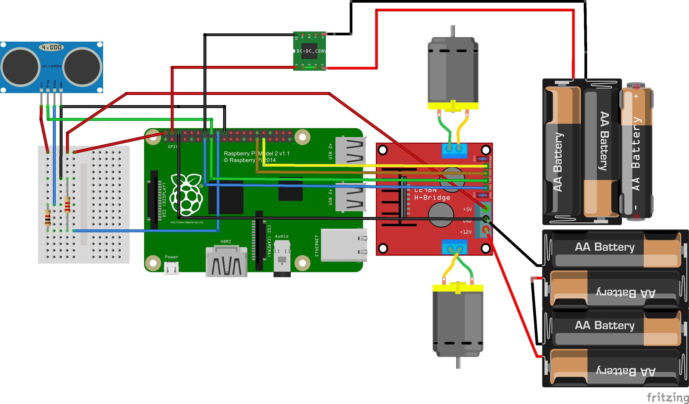
Step 2: Connect the L298N Motor ControllerThere are 4 connections for the motor controller.
From the front there are 3 OUT pins and 4 IN pins.
- OUT pins at the front in order: 12V, Ground, 5V.
IN pins will connect to the GPIO pins on the Raspberry Pi. 2 for each motor on the left and right.
Left:
- 2 IN pins.
Right:
- 2 IN pins.
The IN pins will connect like this: Motor controller = GPIO
- IN1 = GPIO 27 (Pin 13)
- IN2 = GPIO 22 (Pin 15)
- IN3 = GPIO 5 (Pin 29)
- IN4 = GPIO 6 (Pin 31)
The OUT pins will connect like this:
- 12V = Positive wire from the Battery Holder.
- Ground = Ground wire from the Battery Holder + Ground (Pin 6) in the Raspberry Pi.
- 5V = 5V power rail in the breadboard.
NOTE: Remove the 5V to enable the jumper located at the back of the Front OUT pins. If not, the 4.5 V power will vary and the 5V may damage the motor controller.
Make sure your diagram looks like this:
The IN will be connected to the second battery and the OUT will be connected to the Pi.
The design of the Converter:
Snip, Strip, Tin and Solder 2 jumper wires to the OUT pins on the Converter. The left will connect to the Raspberry Pi.
NOTE: Rotate the potentiometer clockwise to lower the voltage going out on the OUT pins. Do this before connecting them to the Raspberry Pi. It needs to be 5 Volts. If not, this can harm your Pi.
Connections for: Converter = Pi
- Positive = Pin 4 (5V)
- Ground = Ground
Your wiring will look like this:
There are four pins: VCC, Ground, Trigger, Echo.
- Connect the 5V power rail on the breadboard to VCC.
- Trigger = Pin 16 (GPIO 23)
- Echo = 1K resistor + Pin 18 (GPIO 24)
- Ground = 2.2K resistor + Ground
It will look like this:
First, connect the Raspberry Pi.
Arduino = Raspberry Pi
- VIN = 5V
- A5 = GPIO 2 (Pin 3)
- A4 = GPIO 3 (Pin 5)
- Ground = Ground
Second, connect the LEDs = Arduino.
- Short = Ground
- Long = Resistor 220
- Resistor + Pin (any you like)


_3u05Tpwasz.png?auto=compress%2Cformat&w=40&h=40&fit=fillmax&bg=fff&dpr=2)
Comments