

Hardware components | ||||||
 |
| × | 1 | |||
 |
| × | 1 | |||
 |
| × | 1 | |||
 |
| × | 1 | |||
| × | 1 | ||||
| × | 1 | ||||
| × | 1 | ||||
Software apps and online services | ||||||
| ||||||
 |
| |||||
 |
| |||||
Hand tools and fabrication machines | ||||||
 |
| |||||
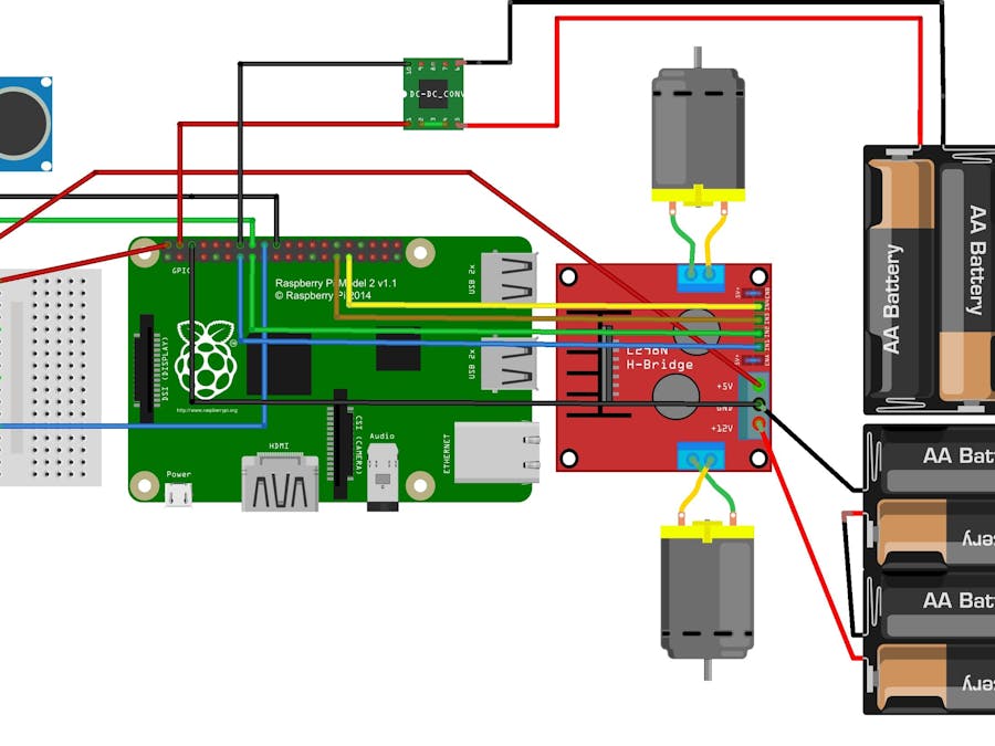
Step 1.b: Connect the Motor Controller
This is the design of the Motor Controller:
The front of the Motor controller have 4 IN pins and 3 OUT pins.
The left OUT pin (+12V) will connect the positive wire on the battery holder.
The middle OUT pin (Ground) will connect the ground wire on the battery holder + Raspberry Pi 2 Pin 14 (Ground)
The right OUT pin (+5V) connect to the 5 Volt power rail on the breadboard.
Connect the IN pins will like this:
IN pin + Raspberry Pi
IN1 + Pin 13 (GPIO 27)
IN2 + Pin 15 (GPIO 22)
IN3 + Pin 29 (GPIO 5)
IN4 + Pin 31 (GPIO 6)
Then connect the Raspberry Pi Pin 2 (5V) to the power rail on the breadboard (where you plug the +5V power from the Motor controller.
Connect the Motor A to the left Motor and Motor B to the right Motor.
NOTE: Remove the 5V Enable jumper to accept the 5V power go to the +5V power. If not, the 4.5V power will be accept.
Make sure your step look like this:
Step 1.c: Wiring up the DC-DC Step up Converter
The design of the Step up Converter
Connect the IN- from the Converter to the Ground wire on the second battery converter and the IN+ to the Positive wire from the battery holder.
Snip, strip, tin and solder the Male head of 2 jumper wires, not the Female one to the OUT pins to the Converter.
NOTE: Rotate the Potentiometer clockwise to lower the voltage go out in the OUT pins. Rotate until it's 5 volts. If not, this can harm your Pi.
Remove the batteries and plug the positive wire from the OUT pins on the Converter to Pin 4 (5V) on the Raspberry Pi and the ground to the Pin 6 (Ground) on the Raspberry Pi. When you put the batteries back in, there will be enough power to drive the Pi without harm.
Now your connection will like this:
Step 1.d: Wire the Ultrasonic Distance Sensor
Before do this, you have to remember these:
First, sport the type of the resistor: 1k Ohm and 2.2k Ohm.
The 1K Ohm have 1 red, 1 black and 1 red.
The 2.2K Ohm have 3 reds.
Second, why we need to use the 1K resistor and 2.2K resistor?
The secret of this question is the Echo pin return 5V while Raspberry Pi is 3.3V. This can burn your Pi.
Now, let's get setup.
Connect the power rail on the breadboard to VCC.
Connect the Trigger pin (marked as Trig) to Pin 16 (GPIO 23).
Connect the 1K resistor from the Echo pin and connect the other end of the resistor to pin 18 (GPIO 24)
Connect the 2.2K resistor from the Ground pin to the jumper pin from the Pin 18 on the Raspberry Pi and connect the Ground pin to the Pin 20 (Ground).
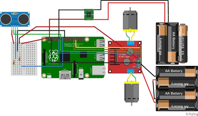
Final of Step 1:
Take a minute to Double check the wiring diagram included with your wiring diagram before powering up the rover.
Step 3: Modify the codeOpen the MainPage.xaml.cs file and look for the // TODO: comment on the code. This TODO comment required you to replace the string YOUR_IOT_DEVICE_CONNECTION_STRING to your IoT Device Connection String. To find your ioT Device Connection String, go to Device Explorer from Azure and then choose the tab Management. Right-click on your device to copy the Connection String and then paste it on the YOUR_IOT_DEVICE_CONNECTION_STRING place. Also, make sure Azure IoT Hub and Microsoft.Azure.Devices.Client Nuget has been installed on this project and check that your IoT device has connected to Azure.


Comments