


Hardware components | ||||||
_ztBMuBhMHo.jpg?auto=compress%2Cformat&w=48&h=48&fit=fill&bg=ffffff) |
| × | 1 | |||
 |
| × | 1 | |||
 |
| × | 1 | |||
 |
| × | 1 | |||
 |
| × | 1 | |||
 |
| × | 1 | |||
 |
| × | 3 | |||
 |
| × | 4 | |||
 |
| × | 1 | |||
 |
| × | 1 | |||
 |
| × | 1 | |||
 |
| × | 1 | |||
 |
| × | 1 | |||
Software apps and online services | ||||||
 |
| |||||
This project demonstrates the working RGB LED using Arduino.
Objective:
Red color glows for the first second and then the Green color glows for the next second followed by the Blue color and this repeats.
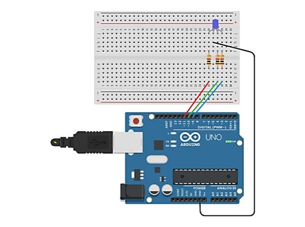
Breadboard Diagram
Make connections as shown in the figure.
RGB: j25, j26, j27, j28
Resistor: f25 and d25
Resistor: f27 and d27
Resistor: f28 and d28
Jumper wire (red): PIN11 (Arduino) and a25 (breadboard)
Jumper wire (green): PIN10 (Arduino) and a27 (breadboard)
Jumper wire (blue): PIN9 (Arduino) and a28 (breadboard)
Jumper wire (black): h26 (breadboard) and GND


1 project • 92 followers
I would like to invite you to join and add your projects to DIYables platform https://www.hackster.io/diyables


Comments