

Hardware components | ||||||
| × | 1 | ||||
_ztBMuBhMHo.jpg?auto=compress%2Cformat&w=48&h=48&fit=fill&bg=ffffff) |
| × | 1 | |||
| × | 1 | ||||
| × | 1 | ||||
| × | 2 | ||||
| × | 1 | ||||
| × | 1 | ||||
Software apps and online services | ||||||
 |
| |||||
 |
| |||||
This project outlines how to build a throttle by wire design (TBW) on a electric bicycle. The TBW acts as a secondary throttle connected to a pedal assist circuit. The throttle can be remotely controlled by pairing with a Bluetooth module, smartphone, and Arduino. My intentions on creating this project were to find a solution on how to regulate speed of a self-driving bicycle via a smartphone application and Bluetooth.
The design is detailed in this tutorial and all parts, files, schematics, and code needed to build the project are included.
The first step in this project is to plan and source all hardware components necessary to complete the build. I have listed all of the required hardware components I used to complete the build above in the parts section.
Since, this project is just attended to be a demonstration of a throttle by wire design feel free to make your own substitutions on your personal build. Additionally, when sourcing the hardware for either a iOS platform vs. Android please make sure you are ordering the correct bluetooth module that pairs with your device ex.) HC-05 for Android vs. HM-10 module for iOS projects.
I also appreciate all comments and suggestions on how to improvise design or new ideas.
Step Two: Part SourcingAll parts can be purchased off of Amazon and through most electronics stores. I have included links of where I have purchased the parts to complete this project. I have also included all files, schematics, and code needed to build the project.
Step Three: Documenting the BuildFirst, lets start off with reviewing the system design.
TBW SYSTEM DESIGN OUTLINE
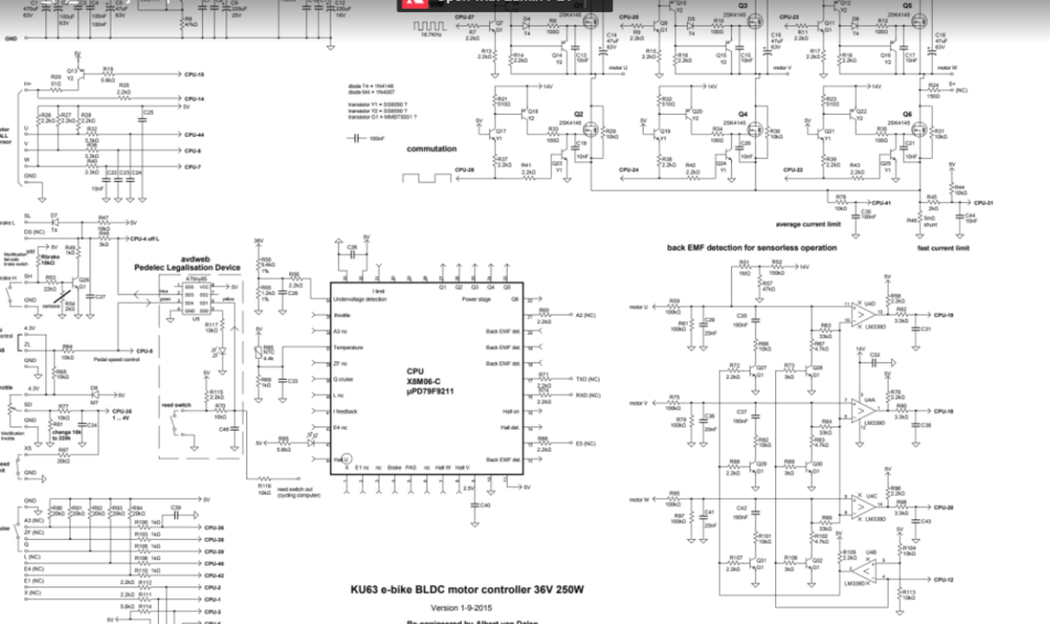
The first part of the system we will review is the 12 amp. 36 volt 350 watt ebike controller. I have provided a schematic for review. The schematic is attached for download.
KU63 ebike controller information can be found at the following page:
BLDC motor 36V 250W
- Maximum current 12A
- Motor HALL sensor or sensorless operation
- Battery undervoltage detection ~27.7V
- Overtemperature protection
- Brake high voltage level and low voltage level input
- Control LED inside
- Weight 200g
- X8M06-C controller IC, TQFP44 housing
- 6 power MOSFETs 2SK4145, RDS(on) 10mΩ, VDSSmax 60V, IDmax 84A
- Quiescent current off-state < 30uA
- Consume current with motor at full speed 60mA (excluding motor current)
- Switching frequency 16.7kHz
- Throttle voltage 1... 4V
I advise to read up on the KU263 ebike controller if you are passionate about ebikes! The design is very hackable and lots of fun projects can be built with this controller and a electric motor.
Every controller is a little different on the circuit and wiring. I have provided the wiring we will use in this project.
Wiring of the controller circuit:
The throttle by wire will be connecting to the pedal assist wire.
Let's now move onto integrating the throttle by wire design into the project.
The Throttle by wire design utilizes the pedal assist circuit on the ebike controller. A Pedal Assist System is found on many ebike controllers.
Let's answer some questions and then we will carryout the buildout of the throttle.
So, how exactly does a Pedal Assist Circuit work? Pedal Assist and a throttle circuit on the same controller?
PEDAL ASSIST SYSTEM: How it is intended to work!
The intention of having a pedal assist system on a ebike is a secondary way of activating the electric motor with a throttle or without on a ebike. Pedal Assist Systems were designed to reduce Human energy consumption of the rider by activating the electric motor in times of need ex.) Hills!
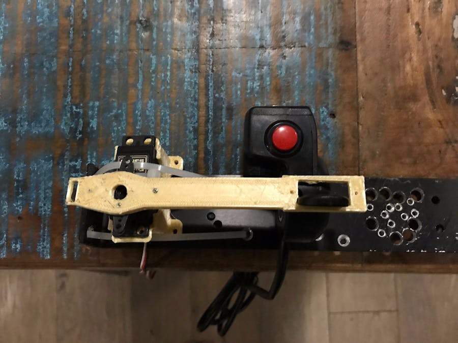
In our case the Pedal Assist System is replaced with a secondary throttle. The first throttle, secondary throttle, and pedal assist system all utilize hall sensors & magnets to communicate with the circuit inside the controller.
Inside both thumb throttles if you break them apart are two magnets on either side of a hall sensor. The hall sensor is a transducer that varies it’s output voltage in response to a magnetic field. Hall effect sensors in the case of the thumb throttle are used to regulate throttle speed. The farther each magnet is away from the sensor results in a different voltage being sent to the controller and the controller sends the voltage to the motor regulating the speed of the motor. The hall effect sensor generates 1-4volts of electrical current inside of the thumb throttle or a standard Pedal Assist System. (1volt when the magnet is far away and 4volts when the magnet is very close to the sensor)
The way the circuit is design in having two throttles works ideal with the smartphone application, servo motor, 3D-printed throttle arm attached to the thumb throttle on the pedal assist circuit because once one throttle is on the other shuts off. This could have applicability of autonomous functioning of a remote throttle by wire mechanism.


Comments