

Hardware components | ||||||
| × | 1 | ||||
| × | 1 | ||||
Software apps and online services | ||||||
 |
| |||||
An analog clock which could hardly be any more analog: This clock gets driven by a continuously running fischertechnik XS motor. By measurement of the turning speed, it gets permanently regulated so that the clock is running just as precise as the time base built into the controller, and especially so that there are no cumulative errors. The software was written in C#/.net and is running on nanoFramework directly inside the controller (https://nanoframework.net).
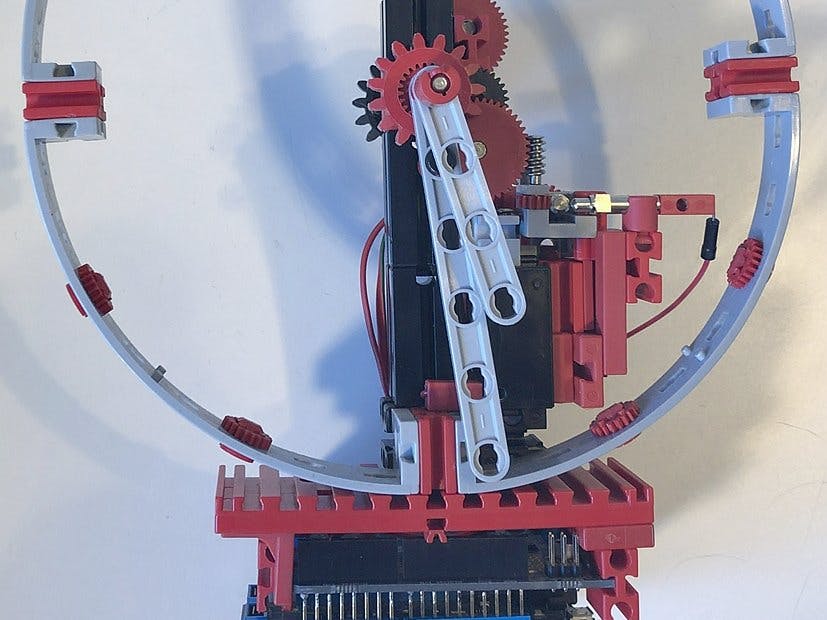
At the same time, this is the most compact clock gear I ever could create. Besides a Z10 (Z10 means a gear wheel with 10 teeth) and a Z15, the gear consists only of gear wheels with fine teeth. The large teeth of the 2nd Z15 are only used to guide the minutes hand. The largest parts of the clock are the clock face, which one could easily just omit, and the hands, which could be used shorter also.
The XS motor which you may recognize in this image's middle drives the fine-toothed gear over three 31069 gear blocks with worm gear. The 9 V motor is running at only about 1 V and therefore turns slowly and, most importantly, silently.
Voltage is applied to the metallic, horizontal worm gear, directly through a 31306 spring contact. At the front (left side of this image), a second spring contact detects whether worm's coil is coming by and makes contact. This way it can be measured using a digital input of the micro controller (a Netduino 3) when the middle one of the three worm gears has completed its turn. This should ideally happen each 3600 / 22 / 14 seconds, which is roughly each 11.69 seconds.
For each turn, the time at which the contact should ideally happen gets computed. This is n * 3600 / 22 / 14 seconds after the start time of the clock, where n is the simply counted expected number of turns. The time of contact gets measured and then the controller computes the amount of voltage which should be put on the motor in order to reach the next contact in ideal time.
The algorithm starts with an initial speed guess (11 % PWM of 9 V) and is self-learning using running averages, how fast the motor runs for a given voltage and so what the needed voltage is to have it run just as fast as needed.
Of course, the motor will reach the exact point of next contact only more or less precise. When the clock starts, it misses the goal with errors above one second, but after only a few cycles, the error is driven down to typically less than 0, 5 seconds and mostly even only 0, 1 seconds or even only a few milliseconds. Because the algorithm deals with pulses coming late, early, or even totally missing due to mechanical tolerances, there are no cumulative errors in the long run. In the end, the clock always runs with errors smaller than one second - a precision which cannot be watched on the hands anyway.
The last metallic worm gear (so, including the one of the motor itself, the 4th) continues to the 2nd plug-in gearwheel of a 31048 mot.2 gear box. On its outside, it has 44 teeth, leading directly to the fine teeth of the Z15 holding the minutes hand. That has 22 teeth, and so we get, counting from the measured worm, 14 teeth of the worm gear and 22 of the Z15. One turn of the minutes hand must take 3600 seconds, and so the worm being measured has to take 3600 / 14 / 22 seconds for one turn.
Here you see how the Z44 passes its turning to the fine 22 teeth of the Z15 (note that this is also a 1:2 reduction seen from the hours hand to the gear). The Z22 is sitting loose in the BS7, 5. It does not fall apart, however, because the Z15 will hold it in place.
The small gear wheel of the Z44 also has 14 teeth and continues to the black 31082 snapping axis with gear wheel Z22 m0, 5. This results in the gear transmission ratio of 14:28 = 1:2. Combined witht the 1:2 ratio mentioned above, this is 1:4.
The gear continues to the back side with a combination of 31915 claw nut with 35133 collet, which both have 22 teeth. The claw nut continues to a 31050 metal axis 50 with gear wheel Z44 m0, 5 of the mot.2 that, again, sits loosely in a BS7, 5. So we get another ratio of 1:2, and so far have (1:2) * (1:2) * (1:2) = 1:8.
Finally, things go on over a standard Z10 to a jamming Z15. This give the missing of 2:3 to get 1:12 from the 1:8 reached so far. This is needed between the minutes and hours hand. To prevent the Z10 axis falling out of the BS7, 5, there is a black 105195 washer 4 15 which gets fixed by a jamming 35981 shell with washer. The black washer stems against the teeth of the Z15.
ElectronicsAt the bottom there is a Netduino 3 carrying an Adafruit motor shield V2. The Netduino runs.net nanoFramework (https://nanoframework.net, open source at https://github.com/nanoframework). On top of that the C# program runs, using my AbstractIO framework (https://github.com/steffalk/AbstractIO).
The fine thing about nanoFramework is that you can use all the comfort that.net and Visual Studio have to offer. This screen shot shows Visual Studio 2017, showing a part of the clock's source code. The program is running, and the debugger is live-watching inside the board. We can set breakpoints, inspect and modify variables and use all the other pleasant features.
On each cycle, the software outputs a status line live to the Visual Studio debug output console. The columns are:
- n = The number of cycles since the start of the clock. One cycle is one turn of the measured worm (thus the 11, 69 seconds already mentioned).
- bounces = The number of detected and ignored contact bounces which occurred in the measurement.
- cycles = The number of turns between this and the previous measurement. This can be greater than 1 when one or more contacts missed.
- vi = The ideal PWM value (that is, the portion of 9V) which, according to the current self-learning of the program, is needed to have one turn in ideal time. This gets averaged using running averages so that variations and inaccuracies in measurement do not lead to large changes, but at the same time the clock is able to adapt to changed conditions, for example due to the slightly easier run when the minutes hand is on the right side or obstacles coming from dust which settled on the gear.
- t1 = The time (since program start) in HH.MM.SS at which the contact ideally should have happened.
- a1 = The time at which the contact actually occurred.
- early/late by: The time interval by which the gear missed the ideal contact time, in seconds and in percent of the cycle time.
- v = The new PWM output by which the motor gets driven for the next cycle. As you see, this gets permanently adapted in order to have the clock lastly run more than precise enough.
The clock is running just perfect since days now and shall continue running for a long time. See it in video:


Comments