Procedure:
1. Start by obtaining all materials for the project.
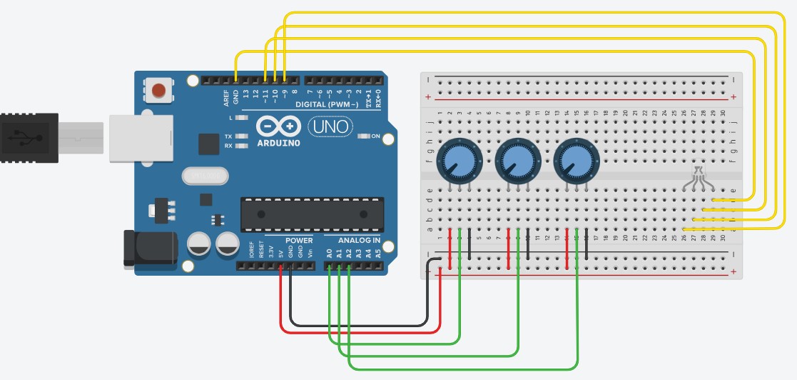
2. Connect the components of the circuit as shown in the circuit diagram.
- Attach the three potentiometers and the RGB LED module to the breadboard, ensuring each of the pins runs on a different connection. The ports of a breadboard are connected as shown in Figure 1.
- Connect the left pin of the potentiometers to the positive bus, and the right pin of the potentiometers to the negative bus. Connect the positive bus to the Arduino Uno 5V (five volt) port, and the negative bus to the Arduino Uno GND (ground) port. The connection to the GND port and 5V port establishes a path for a signal to flow through the potentiometer. The GND port represents a negative signal connection (signal received), and the 5V port represents a positive signal connection (signal given).
- Connect the center pin of each potentiometer (for red, green, and blue) to the analog in ports A0, A1, and A2 respectively. This connection will allow the value of the potentiometer (how much the dial is turned) to be read as input.
- Connect the rightmost pin of the RGB LED module to the GND port on the opposite side of the Arduino Uno from previous connections. Again, this port will serve as a negative signal connection (signal received).
- Connect the red, green, and blue pins of the RGB LED module to the digital ports 11, 10, and 9 respectively. These ports will allow a signal to be passed to the RGB LED module.
3. Add code to the Arduino circuit using the Arduino Web Editor ( $ https://create.arduino.cc/editor $ ). Sample code is provided for reference. This code initializes and sets up ports, measures input from the potentiometer and scales it, and concludes by outputting this value to the RGB LED module.
4. Test the completed circuit, and enjoy the lights!
Figure 1: Breadboard Connections (Digilent. (2014). Breadboard Basics. Learn.Digilentinc. https://learn.digilentinc.com/Documents/180)


_ztBMuBhMHo.jpg?auto=compress%2Cformat&w=48&h=48&fit=fill&bg=ffffff)


Comments