

Hardware components | ||||||
_ztBMuBhMHo.jpg?auto=compress%2Cformat&w=48&h=48&fit=fill&bg=ffffff) |
| × | 1 | |||
| × | 1 | ||||
| × | 1 | ||||
 |
| × | 1 | |||
| × | 1 | ||||
 |
| × | 1 | |||
 |
| × | 1 | |||
Software apps and online services | ||||||
 |
| |||||
(This post is based on a post that was first published on Sept 19th, 2017 on Medium, and has been updated and more current here, including details of the publication of the library and example(s) on GitHub).
In this post, I’m going to show you how I built an Arduino energy monitor and data logger that would help me to gather current and energy data for different loads easily, and plot that information using a program like Excel.
(the updated V2 board is now available!).
Some of you might be aware that I’ve created a new energy monitoring breakout board that I call Dr. Wattson (which is based on the #Microchip #MCP39F521, a power monitoring IC) along with an #Arduino library and #Python library (for boards like #RaspberryPi and #BeagleBoneBlack) for easy integration of quality energy data into your next project! If you haven’t heard of it and would like more information, check out https://upbeatlabs-wattson.launchrock.com/ for more information. It is also available on ProtoStax.
To help me study the energy characteristics of different loads, I went ahead and created an Arduino Energy Monitor and Data Logger, which is the subject of this post!
It consists of an Arduino (of course!) talking to the Dr. Wattson board to get energy data, along with an SD card to write the data to. I’ve also added a button to toggle the data logging, along with an LED indicator to show when data is being logged. The button along with the LED made it really easy to initiate data logging when I had the appropriate load plugged in.
To facilitate the logging and subsequent analysis, I also implemented a log rotation scheme, so each run will be logged to a different file. The output is in CSV format, which means it can be easily imported to Excel (or Numbers on Mac or other equivalent), and the data plotted.
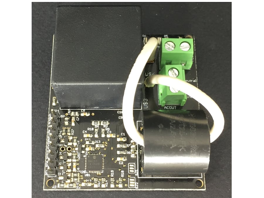
I placed the Dr. Wattson board in an acrylic enclosure so that the AC wires are enclosed, and you can use it in a safe manner! Like so:
I later updated the enclosure a bit and it is now available on Tindie. This is what it looks like now. A little more cleaned up with and additional IEC socket, and spade connectors for easy connections.
I have prepared a User Manual showing how the wiring is to be done, which is now available on GitHub.
The digital out that is coming from Dr. Wattson is completely isolated from the mains, as the energy measurement is done in an isolated manner using current and voltage transformers, so the digital out is perfectly safe to handle.
Once in the enclosure, all you need to do is plug the cable into an existing outlet, and plug any device into the outlet on the enclosure — the PCB is designed for currents up to 12A, so it is quite well built! It is calibrated to measure currents up to 4A (so I could be able measure really small currents for measuring standby power — the MCP39F521 chip on which it is based has a 4000:1 dynamic ratio, meaning it can measure from 4A down to 1mA)
[Update: The Dr. Wattson Energy Monitoring Board V2 now comes configured and calibrated to measure up 15A (from about 4mA)]
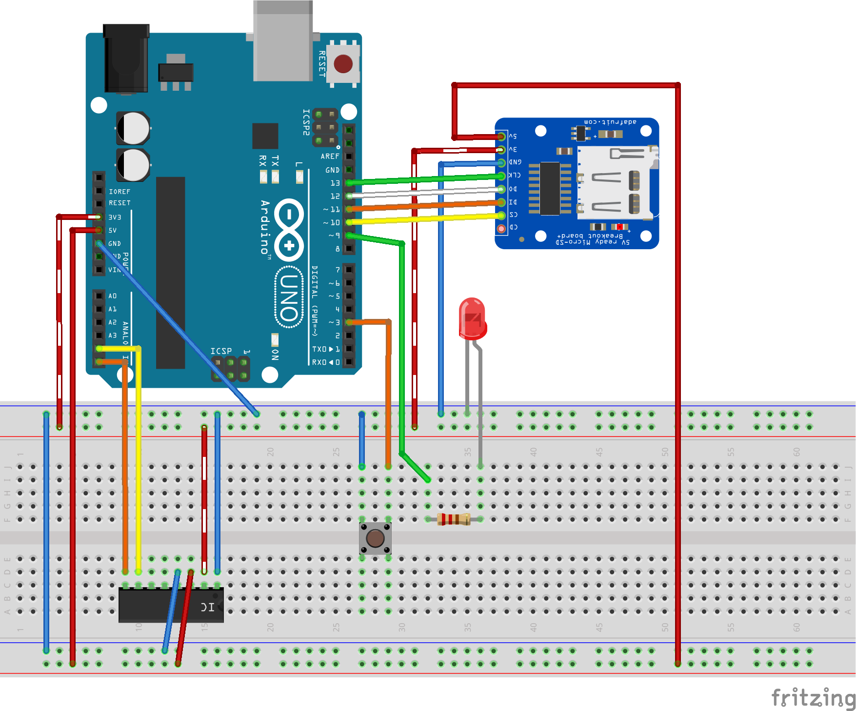
Here is the circuit I used:
I used an SD card breakout similar to the Adafruit one (so I used that in Fritzing, as that was the closest part). The connection is pretty standard — CLK (Arduino Uno pin 13), MISO (Arduino Uno pin 12), MOSI (Arduino Uno pin 11) and CS (Chip select). CS is configurable, though it defaults to pin 10 for hardware CS — I just use that.
For the button, I use the Button library by Jack Christensen, which provides debouncing and a variety of useful stuff in an easy to use package. (https://github.com/JChristensen/Button). The button is using the Arduino’s internal pullup, so it doesn’t have any external pullups and also uses inverted logic (high is OFF, low is ON) — all of these are configurable as parameters to the Button constructor! I’ve hooked up the button to pin 4, but you can use any available pin you like.
I really did not have the time and patience to model Dr. Wattson as a new part in Fritzing, so I cheated, and used the advice of Z-HUT to easily whip up a custom part without much ado. I highly recommend watching it! https://www.youtube.com/watch?v=dfxx8wF3Uhs — thanks Z-HUT! :-)
The only downside is that I have to be content to use the breadboard image of the “generic IC” part that I modified to represent Dr. Wattson. C’est la vie!
Here is a look at Dr. Wattson’s pins (from left to right):
- SCL — for I2C communication, goes to Arduino Uno A5
- SDA — for I2C communication, goes to Arduino Uno A4
- ZCD — Zero Cross Detection — we are not using this feature in this example
- Event — Event indicator — we are not using this feature in this example
- GND — Connect to Arduino GND
- VIN — Connect to Arduino 5V
- 3.3v — Connect to Arduino 3.3v
- GND — Connect to Arduino GND (you only need to connect one of the GND pins)
Ok, now to move on to the actual programming!
Let me first start by explaining the sketch. In setup(), I first set up the SD card communications, and Dr.Wattson communications by calling their respective begin() methods.
// see if the card is present and can be initialized:
  if (!SD.begin(CHIP_SELECT)) {
    Serial.println(F("Card failed, or not present"));
    // don't do anything more:
  }

  wattson.begin(); // Pass in the appropriate address. Defaults to 0x74
I also initialize the LED pin as OUTPUT.
// initialize the digital pin as an output.
  pinMode(LED, OUTPUT);
The button is declared globally so I don’t have to do anything in setup for the button.
#define BUTTON_PIN 4       //Connect a tactile button switch (or something similar)
                           //from Arduino pin 4 to ground.

#define PULLUP true        //To keep things simple, we use the Arduino's internal pullup resistor.
#define INVERT true        //Since the pullup resistor will keep the pin high unless the
                           //switch is closed, this is negative logic, i.e. a high state
                           //means the button is NOT pressed. (Assuming a normally open switch.)
#define DEBOUNCE_MS 20     //A debounce time of 20 milliseconds usually works well for tactile button switches.Button myBtn(BUTTON_PIN, PULLUP, INVERT, DEBOUNCE_MS);    //Declare the button
My data logging is done in files with a name like DATAXX.CSV, where XX is a number (from 00 to 99, so a 100 files). I check the SD card for existing file names, and pick the latest unused file name — for example DATA15.CSV
char filename[] = "DATA00.CSV";
setup() {   ...
   // create a new file
   for (uint8_t i = 0; i < 100; i++) {
      filename[4] = i/10 + '0';
      filename[5] = i%10 + '0';
      if (! SD.exists(filename)) {
         Serial.print(F("Data file is ")); Serial.println(filename);
         // only open a new file if it doesn't exist
         break;  // leave the loop! filename will now be the one we desire
      }
   }
...
}
In the loop() function, once the button is pressed, it toggles the readData variable, which controls if I read the energy data.
void loop() { ...
 myBtn.read();                    //Read the button
  if (myBtn.wasReleased()) {       //If the button was released, change the LED state
        readData = !readData;
        digitalWrite(LED, readData);
  }

  if (readData) {
     ... // read data and save to SD card, etc ....
...
}
Once readData is toggled, I read the energy data from Dr. Wattson, and also record the time:
UpbeatLabs_MCP39F521_FormattedData fData;
    int readMCPretval = wattson.readMCP39F521(&data, NULL);
    unsigned long currentMillis = millis();
and write it out to SD card:
// if the file is available, write to it:
      File dataFile = SD.open(filename, FILE_WRITE);      if (dataFile) {
        dataFile.print(currentMillis);
        dataFile.print(",");
        dataFile.print(fData.currentRMS);
        dataFile.print(",");
        dataFile.print(fData.activePower);
        dataFile.print(",");
        dataFile.print(fData.reactivePower);
        dataFile.print(",");
        dataFile.println(fData.apparentPower);

        // print to the serial port too:
        dataFile.close();
      }
      // if the file isn't open, pop up an error:
      else {
        Serial.print(F("error opening ")); Serial.println(filename);
      }
If the button is toggled again, I stop the data reading/recording.
Action!Once I compiled and uploaded the sketch to my Arduino, getting energy data was pretty easy.
I plugged in the load of choice — a CFL lamp. I wanted to see the current and energy consumption from a cold-start perspective, as well as a warm-start. I plugged in the lamp, but didn’t turn it on.
I pressed the button on my circuit to start the energy measurements — when it was logging, the RED LED told me so! I then turned on the CFL Lamp, and waited until the I thought I had gotten enough data — you see, the CFL, when starting off, consumes more energy than advertised (in my case, a 14W CFL bulb), and then settles down eventually to about 14W. I waited until the readings had settled down. I then pressed the button to turn off the reading.
I could now eject my SD card and start looking at the data!
PS — To log data from additional devices, all you have to do is reset the Arduino — it will pick the next available DATAXX.CSV to log the data into, so you can easily keep the data separate.
Note: Instead of using the Arduino Serial Monitor, I use the built-in “screen” command on my Mac terminal as a serial terminal. In my Sketch, I print the energy data to Serial, and also issue a “clearscreen” command, so the output doesn’t move
Serial.write("\x1B" "c"); // Clear the screen on a regular terminal
wattson.printMCP39F521Data(&data);
This only works on a regular terminal that can accept terminal commands like the above, and does not work on the Arduino Serial Monitor unfortunately. However, once you try screen, you may never go back to Arduino Serial Monitor!
The command will be something like this:
$ screen /dev/tty.usbmodem1411 9600where the first parameter is the “serial port”, and the second is the speed you have configured for your Serial connection in your Arduino sketch.
Plotting the data in ExcelBecause the file in CSV format, loading it and plotting it in Excel was pretty easy. I shall not go into the details here, as there are many tutorials for creating a chart in Excel. I inserted a row containing the column headers
timestamp, currentRMS, activePower, reactivePower, apparentPower(note to self — this will be a future enhancement to my Sketch — to add the column headers in the CSV directly!)
I chose the above datapoints to log and plot. Current consumption over time is obviously interesting. Why activePower, reactivePower and apparentPower? Based on the electrical characteristics of the device, it can be a resistive load, a reactive load, or somewhere in between, and the three power parameters thus tell us its overall characteristics, and also if they change over time. Or so I think…
Let’s take a look at my results for a CFL Lamp from a cold start:
A note on the units: the current is A/10000 and energy is W/100 — these allow the values to be in the same range for plotting together to see trends.
The current peaks at around 0.21 amps before eventually settling to about 0.18 amps.
The active power peaks at about 17 watts before eventually settling to about 14.2 watts.
After it had settled, I switched off the CFL and waited for a little while, before turning it back on again (hence the drop in the current in the chart above). You can see that once a CFL has “warmed up”, it quickly settles to it steady state consumption.
ConclusionThere’s a lot of interesting data and experiments you can do with energy data from your appliances and devices. I was excited to start getting my hands on some data and sharing them with you!
My goal with Dr. Wattson is to enable quality energy data for the Maker and make it more accessible, so you can use it as a building block for your wild and crazy ideas.
Dr. Wattson is designed to be safe to use (especially with the enclosure), comes calibrated (so you can get quality energy data right away), but also exposes more complex functionality for the serious user
- calibration routines
- ZCD (Zero Crossing Detector)
- Event notification (over-current, over power, voltage sag/surge events)
- the ability to customize the range of readings (by modifying burden resistors and or CT and recalibrating using above-mentioned calibration routines),
- using multiple Dr. Wattsons together with a single MCU (by changing configurable I2C addressing).
If you are interested in energy monitoring and like Dr. Wattson, please sign up at (https://upbeatlabs-wattson.launchrock.com/) to stay abreast of news and updates!
Cheers,
Sridhar
Here is the entire Sketch, for your reference! You can also find it and the Dr. Wattson library, along with a host of other examples at the Upbeat Labs drwattson GitHub repository.
/*******************************************************************************
 This is a example sketch for Upbeat Labs Dr. Wattson Energy Monitoring Breakout
 --> https://www.tindie.com/products/UpbeatLabs/dr-wattson-energy-monitoring-board-2/
 This example demonstrates getting Energy Data from Dr. Wattson and writing
 it to an SD card in a comma separated (CSV) format. A button is used to
 toggle the data collection, so you can log the data when you are ready.
 When the button toggles the measurement, the sketch starts to poll the
 module for Energy data and prints it out. For ease of seeing the values,
 use a program like screen to display the Serial output. The serial writes
 the characters necessary to clear the screen on a regular terminal, which
 means that the serial output will stay in place and just update over time.
 Turn on the input power to see the voltage RMS, line frequency values
 change to the appropriate values.
 Turn on the load attached to your output to see current RMS, power factor,
 active, reactive and apparent power values change.
 All these values are written to the SD card in CSV format, which can then
 be used with a program like Excel to view/plot the data. The file name is
 of the form DATAnn.CSV. At the time of setup, a new file name is chosen that
 does not already exist, so the files will be DATA00.CSV, DATA01.CSV, DATA02.CSV
 and so on. The logging rotates to new files until DATA99.CSV.
 The communication happens over I2C. 2 pins are required to interface.
 There are 4 selectable I2C address possibilities per board (selectable
 via two solder jumpers (that select each pin to be high or low). Based
 on this, there are 4 possible addresses:
 I2C address  SJ1   SJ2
 0x74         LOW   LOW
 0x75         LOW   HIGH
 0x76         HIGH  LOW
 0x77         HIGH  HIGH
 Dr. Wattson has two outputs, ZCD or Event, that are
 used for notifications, and therefore will usually be
 connected to an externally interruptable pin
 (like pin2 or pin3 on Arduino Uno). In this example,
 ZCD and Event are not used.
 Button is connected to pin 4.
 * SD card attached to SPI bus as follows:
 ** MOSI - pin 11
 ** MISO - pin 12
 ** CLK - pin 13
 ** CS - pin 10
 LED is connected to pin 9
 Written by Sridhar Rajagopal for Upbeat Labs LLC.
 BSD license. All text above must be included in any redistribution
*/
#include <Wire.h>
#include "UpbeatLabs_MCP39F521.h"
#include <SD.h>
#include <Button.h>        //https://github.com/JChristensen/Button
#define BUTTON_PIN 4       //Connect a tactile button switch (or something similar)
                          //from Arduino pin 4 to ground.
#define PULLUP true        //To keep things simple, we use the Arduino's internal pullup resistor.
#define INVERT true        //Since the pullup resistor will keep the pin high unless the
                          //switch is closed, this is negative logic, i.e. a high state
                          //means the button is NOT pressed. (Assuming a normally open switch.)
#define DEBOUNCE_MS 20     //A debounce time of 20 milliseconds usually works well for tactile button switches.
Button myBtn(BUTTON_PIN, PULLUP, INVERT, DEBOUNCE_MS);    //Declare the button
#define LED 9 // Connect an LED (via a 220ohm resistor) from pin 9 (anode) to GND (cathode).
#define CHIP_SELECT 10
UpbeatLabs_MCP39F521 wattson = UpbeatLabs_MCP39F521();
bool readData = false;
char filename[] = "DATA00.CSV";
void setup() {
 Serial.begin(9600);  //turn on serial communication
 Serial.println(F("**Upbeat Labs Dr. Wattson Example Sketch**"));
 Serial.println(F("Upbeat Labs Dr. Wattson Energy Data SD Card Logging Example Sketch"));
 Serial.println(F("******************************************************************"));
 // initialize the digital pin as an output.
 pinMode(LED, OUTPUT);
 pinMode(CHIP_SELECT, OUTPUT);
 // see if the card is present and can be initialized:
 if (!SD.begin(CHIP_SELECT)) {
   Serial.println(F("*** SD Card failed, or not present ***"));
   // don't do anything more:
 }
 wattson.begin(); // Pass in the appropriate address. Defaults to 0x74
 // create a new file
 for (uint8_t i = 0; i < 100; i++) {
   filename[4] = i/10 + '0';
   filename[5] = i%10 + '0';
   if (! SD.exists(filename)) {
     Serial.print(F("Data file is ")); Serial.println(filename);
     // only open a new file if it doesn't exist
     break;  // leave the loop! filename will now be the one we desire
   }
 }
 Serial.println(F("**initialization complete.**"));
}
void loop() {
 myBtn.read();                    //Read the button
 if (myBtn.wasReleased()) {       //If the button was released, change the LED state
       readData = !readData;
       digitalWrite(LED, readData);
 }
 if (readData) {
   UpbeatLabs_MCP39F521_Data data;
   UpbeatLabs_MCP39F521_FormattedData fData;
   int readMCPretval = wattson.read(&data, NULL);
   unsigned long currentMillis = millis();
   if (readMCPretval == UpbeatLabs_MCP39F521::SUCCESS) {
     // Print stuff out
     Serial.write("\x1B" "c"); // Clear the screen on a regular terminal
     wattson.convertRawData(&data, &fData);
     printMCP39F521Data(&fData);
     // if the file is available, write to it:
     File dataFile = SD.open(filename, FILE_WRITE);
     if (dataFile) {
       dataFile.print(currentMillis);
       dataFile.print(",");
       dataFile.print(fData.currentRMS);
       dataFile.print(",");
       dataFile.print(fData.activePower);
       dataFile.print(",");
       dataFile.print(fData.reactivePower);
       dataFile.print(",");
       dataFile.println(fData.apparentPower);
       // print to the serial port too:
       dataFile.close();
     }
     // if the file isn't open, pop up an error:
     else {
       Serial.print(F("error opening ")); Serial.println(filename);
     }
   } else {
     Serial.print(F("Error!")); Serial.println(readMCPretval);
   }
 }
}
void printMCP39F521Data(UpbeatLabs_MCP39F521_FormattedData *data)
{
 Serial.print(F("Voltage = ")); Serial.println(data->voltageRMS, 4);
 Serial.print(F("Current = ")); Serial.println(data->currentRMS, 4);
 Serial.print(F("Line Frequency = ")); Serial.println(data->lineFrequency, 4);
 Serial.print("Analog Input Voltage = "); Serial.println(data->analogInputVoltage, 4);
 Serial.print(F("Power Factor = ")); Serial.println(data->powerFactor, 4);
 Serial.print(F("Active Power = ")); Serial.println(data->activePower, 4);
 Serial.print(F("Reactive Power = ")); Serial.println(data->reactivePower, 4);
 Serial.print(F("Apparent Power = ")); Serial.println(data->apparentPower, 4);
}


Comments