


Reading Data From The Cartridge
Original post: hereROM dumper: here
I recently got given an original Sega mega drive and after completing the first couple of worlds on Sonic I started to wonder what else I could do with it. I thought the easiest thing would be to try and read the data from a cartridge as all you need to do it write the required address to the 23 pin address bus and then read the bits from the 16 pin data bus. My arduino mega has more than enough pins and so can read a cartridge with no external components other than cartridge connector.
The closest thing the 32x2 way card slot I could find was a 31x2 way ISA slot on an old 486 motherboard. Thankfully the outermost pins on one end of the cartridge are made up of an unused pin and a redundant ground connection and so can be safely left unconnected. After de-soldering it I used a file to remove the plastic so I could physically get the cartridge in. (Left side in the image below.)
Fitting The Cartridge
Fitting The Cartridge
*=active low

a1  - gnd    b1  -
a2  - +5v    b2  -
a3  - A8     b3  -
a4  - A11    b4  - A9
a5  - A7     b5  - A10
a6  - A12    b6  - A18
a7  - A6     b7  - A19
a8  - A13    b8  - A20
a9  - A5     b9  - A21
a10 - A14    b10 - A22
a11 - A4     b11 - A23
a12 - A15    b12 -
a13 - A3     b13 -
a14 - A16    b14 -
a15 - A2     b15 -
a16 - A17    b16 - *OE
a17 - A1     b17 - *CS
a18 - gnd    b18 - *AS
a19 - D7     b19 -
a20 - D0     b20 -
a21 - D8     b21 -
a22 - D6     b22 - D15
a23 - D1     b23 - D14
a24 - D9     b24 - D13
a25 - D5     b25 - D12
a26 - D2     b26 -
a27 - D10    b27 - *RESET
a28 - D4     b28 - *WE
a29 - D3     b29 -
a30 - D11    b30 -
a31 - +5v    b31 -
a32 - gnd    b32 - gnd
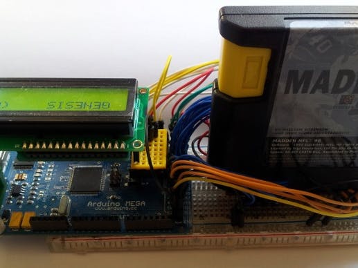
Example output from the arduino serial monitor (from 'Castle of Illusion' and 'Madden NFL 96'):
I added ZX-400P 2 line LCD connected to TX1 & some simple R to L scrolling code:
Cartridge Testing
The device has been tested with all the cartridges I have to hand: Sonic the Hedgehog, Altered Beast, Desert Strike, Madden NFL 94, NFL 93, Castle of Illusion and Madden NFL 96.
Pins
The 'b' side (b1-b32) is the front side of the cartridge and 'a' the rear. a1 and b1 are the two pins that I've left unconnected due to the the ISA connector being too short. The 'A' pins (A1-A23) are the address bus and the 'D' pins (D0-D15) are the 16 bit data bus. I've wired every pin on both buses to it's own digital IO pin on the arduino mega - it doesn't really matter which ones as long you make a note of the mapping. I did have a problem using 20 and 21 as these seem to have 20k Ohms across them which may be to do with them also being the i2c pins. OE and CS are grounded but everything seemed to work even when they were disconnected.
The test code below reads from address 0x80 (word aligned) - which is the location of the 'SEGA' licencing string and is usually followed by either 'GENESIS' or 'MEGA DRIVE', the release date and game title - until it hits a null byte then it starts again at 0x80.
The A[23] array is the arduino pin to address line mapping - A[0] is A1, A[1] is A2 etc. The D[16] array is the pin to data line mapping - D[0] is D0, D[1] is D1 etc.
Pin Mapping

Comments