
Hardware components | ||||||
 |
| × | 1 | |||
 |
| × | 1 | |||
 |
| × | 1 | |||
Software apps and online services | ||||||
 |
| |||||
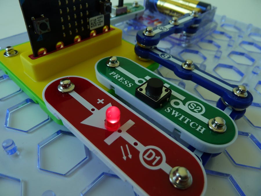
The snap:bit is an electronic component for the Snap Circuits educational electronic kit. It features a socket for connecting the BBC micro:bit. This allows the Snap Circuits to be programmatically controlled by the micro:bit.
This project demonstrates how to combine two different components from Snap Circuits to work with the BBC micro:bit.
One component, the Press Switch (S2), will be used as input to the micro:bit for changing the status of the second component, the Red LED (D1). If the press switch is pressed, the LED will turn on. If pressed again, the LED will turn off.
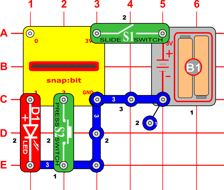
Snap Circuits diagramBuild the circuit shown in the diagram above.
CodeYou can build the code yourself in the MakeCode Editor. You will find the "digital write pin" block under the Advanced > Pins section. The "on pin pressed" block is under the Input section.
Alternatively, open the ready project here: https://makecode.microbit.org/_EWXe62fbXbzr
Once ready, download the code to your micro:bit. Then disconnect all cables from your micro:bit. Both the USB and the battery pack must be disconnected from the micro:bit.
How it works...When you close the slide switch (S1), the Battery Holder (B1) powers the snap:bit through the 3V snap and the micro:bit turns on. The “on start” event triggers and the micro:bit displays the snap:bit logo.
Press the press switch (S2) and release it within 1 second. This closes the circuit between the P2 and GND pins of the micro:bit. The “on pin P2 pressed” event triggers and the micro:bit writes a digital 1 signal to pin P1. This closes the circuit between the P1 and GND pins and the LED (D1) turns on.
Press and release the press switch once again. The “on pin P2 pressed” event triggers once again. This time the micro:bit writes a digital 0 signal to pin P1. This opens the circuit between the P1 and GND pins and the LED turns off.
Note that the code uses a helper variable with the name “on”. When the micro:bit writes a digital 1 signal to pin P1, it sets “on” to 1. When the micro:bit writes a digital signal 0 to pin P1, it sets “on” to 0. The value of the “on” variable is checked every time the “on pin P2 pressed” event triggers. This helps the micro:bit alternate writing digital 0 and 1 signals to pin P1 every time the press switch (S2) is pressed.


Comments