
Hardware components | ||||||
 |
| × | 1 | |||
 |
| × | 1 | |||
 |
| × | 1 | |||
| × | 1 | ||||
Software apps and online services | ||||||
 |
| |||||
The snap:bit Is an electronic component for the Snap Circuits educational electronic kit. It features a socket for connecting the BBC micro:bit. This allows the Snap Circuits to be programmatically controlled by the micro:bit.
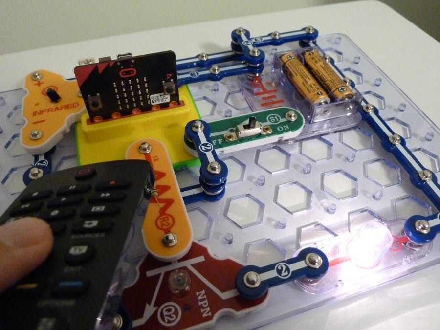
This project demonstrates how to use a standard TV remote control to send an infrared (IR) signal to the BBC micro:bit to light the 3V Lamp (L1) of Snap Circuits. The micro:bit will automatically turn the lamp off 5 seconds later.
This project builds on top of what we learned in the Connect Infrared Receiver and the Control Lamp With Transistor projects.
As mentioned in the Connect Infrared Receiver project, decoding the exact command pattern from the IR remote control requires quite some coding. This project will take a simple way of turning the light on when any of the buttons of the remote control is pushed.
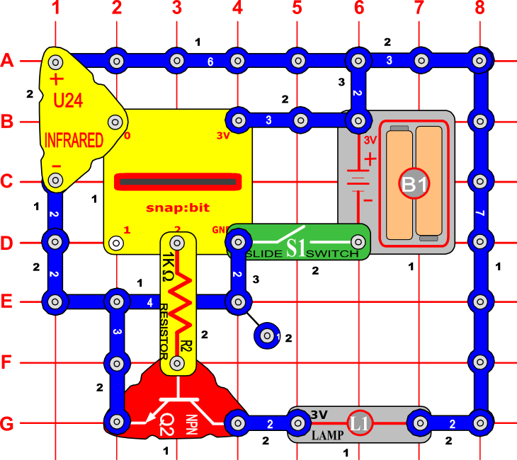
Snap Circuits diagramBuild the circuit shown in the diagram above.
CodeYou can build the code yourself in the MakeCode Editor. You will find the "analog read pin" and "digital write pin" blocks under the Advanced > Pins section.
Alternatively, open the ready project here: https://makecode.microbit.org/#pub:_5Pb53VhkU8L0
Once ready, download the code to your micro:bit. Then disconnect all cables from your micro:bit. Both the USB and the battery pack must be disconnected from the micro:bit.
How it works...When you close the slide switch (S1), the Battery Holder (B1) powers the snap:bit through the 3V snap, and the micro:bit turns on. In parallel, the batteries power the Infrared Receiver (U24) through its positive (+) terminal.
At this moment no current flows from pin P2 of the micro:bit to the base of the NPN transistor (Q2). Therefore, no current flows between the collector and the emitter of the transistor, so that part of the circuit is open and the Lamp (L1) is off.
The “forever” loop starts. It repeatedly reads the analog input from pin P0 where the infrared receiver is connected to.
If you push a button on the IR remote control, it will emit an infrared wave signal to the Infrared Receiver (U24). The receiver will detect it and the analog read from pin P0 will return a low value (< 100).
In response to the received IR signal, the micro:bit will write a digital 1 signal to pin P2. This closes the circuit between the P2 and GND pins and a small current starts flowing to the base of the NPN transistor, through the transistor's emitter, the GND pin of the snap:bit, and back to the negative terminal of the Battery Holder (B1).
The small amount flowing through the base of the transistor is enough to trigger the current flow from the collector to the emitter. A large amount of current (up to 200 mA) starts flowing from the positive terminal of the Battery Holder (B1), through the Lamp (L1), the collector and emitter of the transistor, the GND pin of the snap:bit, and back to the negative terminal of Battery Holder (B1). The part of the circuit connected to the lamp is now closed and the lamp turns on.
The micro:bit waits for 5 seconds and then writes a digital 0 signal to pin P2. This opens the circuit between the P2 and GND pins and the current stops flowing to the base of the transistor. This stops the current flow from the collector to the emitter of the transistor and the lamp turns off.
While the micro:bit waits for the 5 seconds to pass, the "forever" loop is blocked. Any IR signals sends from the remote control are discarded.


Comments