
Hardware components | ||||||
 |
| × | 1 | |||
 |
| × | 1 | |||
 |
| × | 1 | |||
| × | 1 | ||||
Software apps and online services | ||||||
 |
| |||||
The snap:bit is an electronic component for the Snap Circuits educational electronic kit. It features a socket for connecting the BBC micro:bit. This allows the Snap Circuits to be programmatically controlled by the micro:bit.
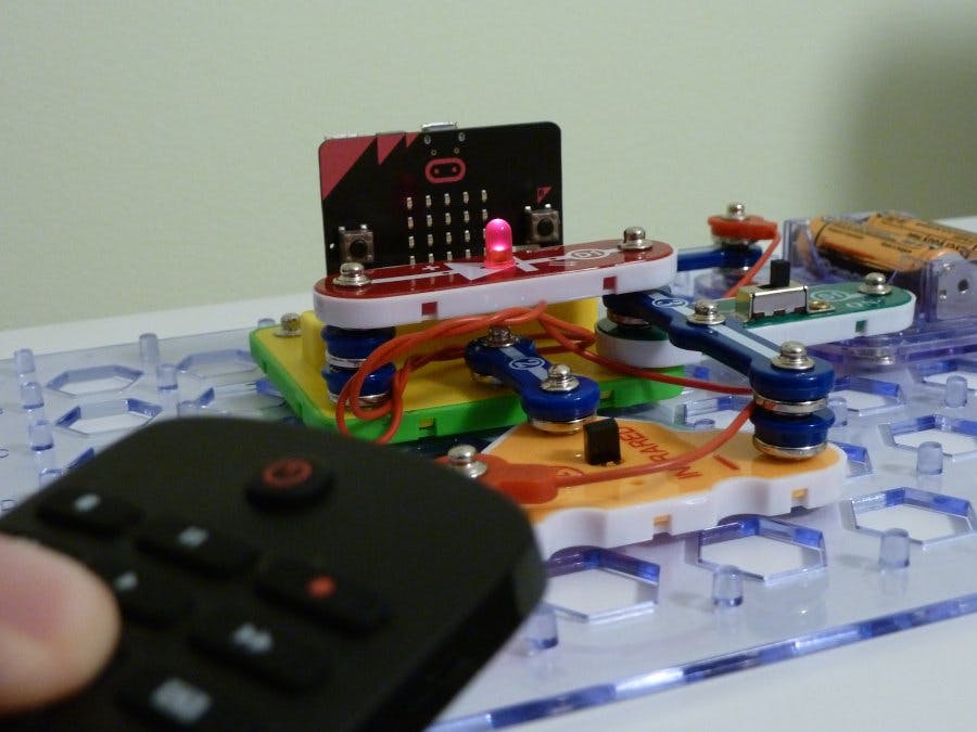
This project demonstrates how to properly connect the Infrared Receiver (U24) of Snap Circuits to the snap:bit board. We will use a standard TV remote control to send infrared (IR) signal to the infrared receiver. The micro:bit will light the Red LED (D1) to indicate that the IR signal has been received.
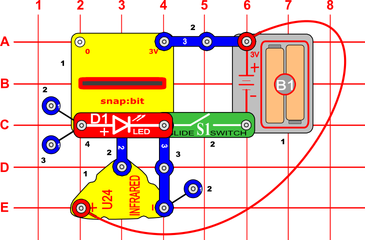
Snap Circuits diagramBuild the circuit shown in the diagram above.
CodeYou can build the code yourself in the MakeCode Editor. You will find the "analog read pin" and "digital write pin" blocks under the Advanced > Pins section.
Alternatively, open the ready project here: https://makecode.microbit.org/#pub:_UzjULHeKMDHe
Once ready, download the code to your micro:bit. Then disconnect all cables from your micro:bit. Both the USB and the battery pack must be disconnected from the micro:bit.
How it works...When you close the slide switch (S1), the Battery Holder (B1) powers the snap:bit through the 3V snap and the micro:bit turns on. In parallel, the batteries power the Infrared Receiver (U24) through the red jumper wire.
The “forever” loop starts. It repeatedly reads the analog input from pin P2 where the infrared receiver is connected to.
When we point the IR remote control to the infrared receiver and push a button, the IR remote control sends a pulse of modulated infrared waves. Each button of the remote control sends a different pulse pattern to the receiver. By decoding the pulse pattern the receiver can detect which button was pushed on the remote control.
Decoding the pulse pattern requires quite some coding, so we will leave it for a future project. In this project, we are just indicating that an IR signal is received if any of the buttons of the remote control is pushed.
Let's go back to the "forever" loop. If there isn't any IR signal received at this moment, the analog read returns a high value - usually greater than 900. If there is an IR signal received, the analog read returns a low value - usually lower than 100.
If the "forever" loop, reads a low value, the micro:bit writes a digital 1 signal to pin P1 where the Red LED (D1) is connected to. This turns the LED on. Otherwise, if the read value is high, the micro:bit writes a digital 0 signal to pin P1, which turns the LED off.
The "forever" loop executes very fast - thousands of times per second. When you push a button on the IR remote control, you will see that the LED will flash several times. This is because it repeats the pattern of the pulse sent by the remote control.


Comments