Stuck at home for St. Patrick's Day? Here is our idea of how to cheer up the day with the many STEM toys you have piled at home.
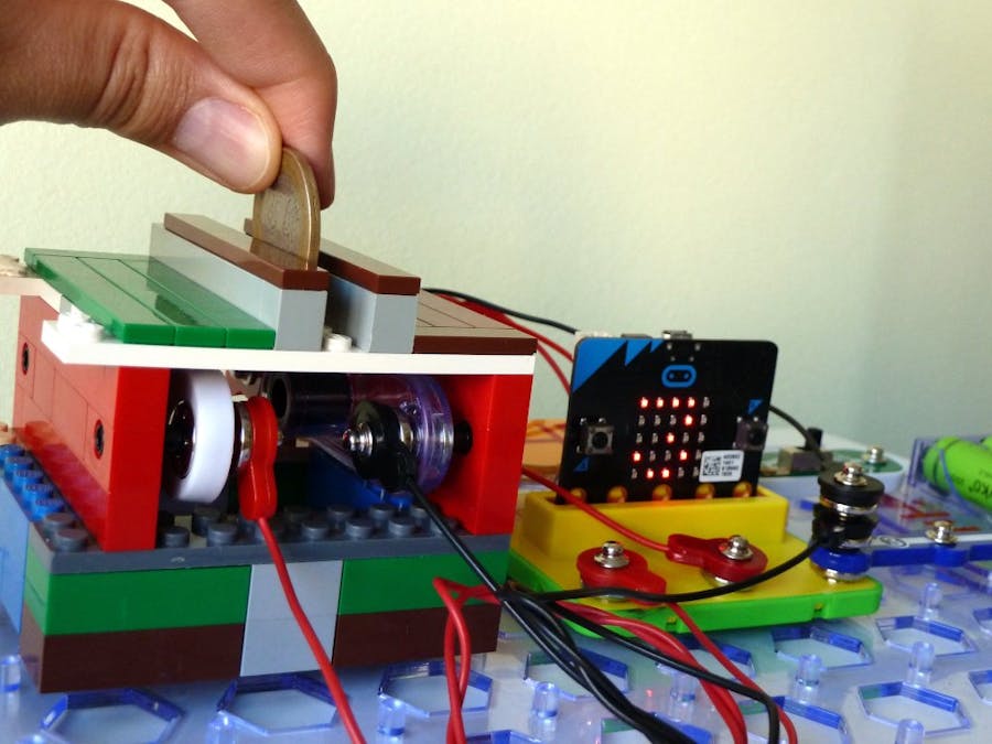
We are going to build a pot of gold that will count the coins you put inside.
We will use these toys:
- Lego bricks - for the pot.
- Snap Circuits - for the electronic circuit that will detect the coins going inside the pot.
- BBC micro:bit - the "smart brain" of the project that will run our code for motion detection and coin counting.
- snap:bit - for integrating the micro:bit with Snap Circuits.
We will use Lego bricks for building the pot of gold. The critical part is attaching the Photoresistor (RP) and Red LED (D1) of Snap Circuits to the Lego bricks.
If you already have the Snap Circuits® Bric: Structures kit, this is quite easy and straight-forwarded. But in this project, we will show you have to do it even without this kit.
You would need some key parts for Lego Technic, but such that are frequently found in regular Lego kits too:
- 4 x Technic Bricks 1 x 2 with Hole
- 4 x Technic Pins
The Technic Pins fit very well inside the bottom of the snap buttons of the Snap Circuits parts.
Use a brick and a pin of each of the snap buttons of the Photoresistor and the Red LED.
Then use whatever Lego parts you have to build the pot of gold around the LED and Photoresistor. Just make sure the LED points directly towards the light sensor of the Photoresistor.
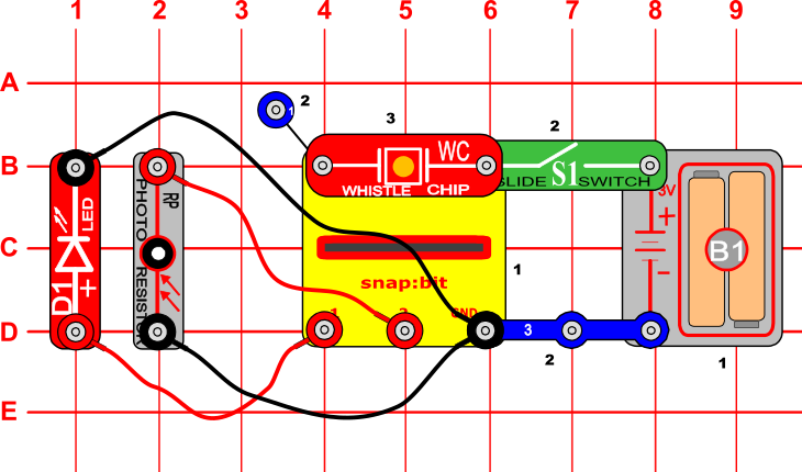
Once ready with the pot of gold, build the circuit shown in the diagram above.
Make sure the connect the positive side of the Red LED (D1) to pin P1 and the negative side - to GND.
Make sure the batteries are not too weak, so the LED beams strong enough light at the photoresistor. Otherwise, motion detection may not work properly. If you don't have strong batteries, you can power the micro:bit from the USB cable.
Motion detectionWe the Red LED and the Photoresistor of Snap Circuits to implement a simple, yet efficient motion detector.
The photoresistor (RP) is a special resistor that can be used as a light sensor. Its resistance value changes from nearly infinite in total darkness to about 1 kΩ when bright light shines directly on it. For details on how it works, check the "Connect Photoresistor to Micro:bit" project. In short, the micro:bit can measure the amount of light the connected photoresistor receives.
We have the LED beaming light directly on the photoresistor to guarantee a constant amount of ambient light on the photoresistor.
When the dropped coin passes between the LED and the photoresistor, the light from the LED is interrupted and the photoresistor increases its resistance. This way, just for a fraction of the second, the micro:bit receives a higher value from the connected photoresistor. This change of value is detected as a coin dropped in the pot of gold.
Let's see how we implement this logic in the code.
CodeYou can build the code yourself in the MakeCode Editor. You will find the blocks in the following sections:
- The "set to" and "change by" blocks are under the Variables section.
- The "digital write pin" and "analog read pin" blocks are under the Advanced > Pins section.
- The "if" block is under the Logic section.
- The "while-do" block is under the Loops section
- The "play tone" block is under the Music section.
- The "pause" and "show number" blocks are under the Basic section.
Alternatively, open the ready project here: https://makecode.microbit.org/_1HgdVE1hKPo5
Once ready, download the code to your micro:bit. Then disconnect all cables from your micro:bit. Both the USB and the battery pack must be disconnected from the micro:bit.
How it works...When you close the slide switch (S1), the Battery Holder (B1) powers the snap:bit through the 3V snap and the micro:bit turns on. The “on start” event triggers and the micro:bit writes a digital 1 signal to pin P1. This lets the current flow through the LED (D1), which turns it on, and back through the GND of the snap:bit and the battery.
Then the micro:bit pauses for 1 second before reading the value from the Photoresistor (RP). This is important to allow enough time for the photoresistor to adapt to the change in ambient light.
Now the micro:bit reads an analog signal from pin P2 where the photoresistor is connected. This value is set to the "normal" variable. This variable now holds the value of the normal ambient light for the photoresistor.
Next, the micro:bit sets the "counter" variable to 0 and displays this initial value on the LED display. This variable counts the number of coins dropped into the pot.
As the "on start" event completes, the micro:bit starts executing the "forever" loop.
At the start of each iteration, the micro:bit will read a fresh value from the photoresistor (connected on pin P2) and will compare it against the value in the "normal" variable. If the value is higher than "normal + 3" then we assume that something (the falling coin!) made a shadow on the photoresistor.
Why "+3"? Well, the value read from the photoresistor fluctuates a little bit - normally +/- 1. To avoid false-positive detections, we make sure that some significant change of the light condition has happened. Usually, a falling coin changes the value with a number between 50 and 200. But this really depends on your current light conditions and the charge of the batteries. So, if the "+3" check does not work well for you, try changing it to another number.
So, we detected that something made a shadow on the photoresistor. Now, we expect that this is a temporary event and the micro:bit will soon start reading the "normal" value from the photoresistor. Thus, we have the "while-do" loop, which does nothing but waiting for the value received from the photoresistor to drop back to the "normal" value. This means that the coin has passed-through and dropped at the bottom of the pot.
When this happens, the micro:bit increases the "counter" variable by one, plays a short "clink" sound and displays the new value on the LED screen.
Then the "forever" loop continues to wait for the next coin to drop...


Comments